Hello,
I am building a closed loop digital class D amplifier using TAS5103 IC from TI as my output stage.
I see that my system goes unstable momentarily and regains control on its own. This is observed by giving a tone input and checking the output of the LC filter in an oscilloscope. The sine wave disappears for a while in between and some random noise is seen during this period.
Any suggestions regarding debugging the issue would be appreciated.
Do I get it right - you are using this simply as output stage of an otherwise quite conventional class-d ampc ?
The idea is not bad because thes are high precision switching stages and there are certain things that you will not have to deal with that way.
But you could probably post the whole schematic such that we could see what you are actually doing.
Maybe it is actually a feedback loop instability but maybe you are also triggering some of the protection functions of that output stage. What is the switching frequency that you are using ? IIRC these TI stages don't tolerate too low switching frequencies (or lost oscillation due to clipping).
Regards
Charles
@phase_accurate, thanks for the reply.
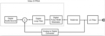
Yes, I am using TAS5103 IC as my output stage. I have attached a top level block diagram of what I am doing.
Switching frequency being used is 384kHz. It is supported by the IC.
As you said, stability of control loop is a possible cause. But ideal simulation of the control loop says the loop is stable.
Attachments
I wasn't aware that you are actually trying to make a digital feedback. What is the sampling rate of the AD-converter in the feedback path ? What advantages do you expect to either use of conventional analog loopback or using the digital modulator from TI ?
When you did the simulation of the ideal loop, did you use an analog model ? Did you take all latencies and sampling effects into consideration ? Do you use a S&H circuit in front of the AD converter ? Which one is your sampling point ?
Regards
Charles
When you did the simulation of the ideal loop, did you use an analog model ? Did you take all latencies and sampling effects into consideration ? Do you use a S&H circuit in front of the AD converter ? Which one is your sampling point ?
Regards
Charles
Major advantages of digital closed loop control are elimination of the frontend DAC thereby saving area and power. In addition, the ADC in the feedback path is not extra as the trend is to integrate speaker protection circuitry with the class D amp, and this requires an ADC.
It's a continuous time delta sigma adc running with a sampling rate of 6.144MHz.
In my simulation, sampling and delays have been taken into consideration. Everything except the TAS5103 IC is modelled.
Thanks
asenapati
It's a continuous time delta sigma adc running with a sampling rate of 6.144MHz.
In my simulation, sampling and delays have been taken into consideration. Everything except the TAS5103 IC is modelled.
Thanks
asenapati
Given that an FPGA is involved, I'd be looking at the digital loop filter implementation to see if there is a possible arithmetic overflow or saturation. This could lead to the kind of output that you are seeing
Hello,
I am building a closed loop digital class D amplifier using TAS5103 IC from TI as my output stage.
I see that my system goes unstable momentarily and regains control on its own. This is observed by giving a tone input and checking the output of the LC filter in an oscilloscope. The sine wave disappears for a while in between and some random noise is seen during this period.
Any suggestions regarding debugging the issue would be appreciated.
First you should try using it without feedback and check if there is any anomaly at any amplitude, any freq.
There are too many error possibilities in closed loop.
Is there any filter in front of the DS-AD converter ? I would say that it would need one in order to cope with the switching signal as input because there is alot of spectral content at even higher frequencies than its sampling frequency.
You said that it was stable when simulated with an ideal model. Did that model also use a delta-sigma converter in the feedback path ? Those can have quite some latency which might also be detrimental to stability. The voltage range driving it is also very critical.
Regards
Charles
You said that it was stable when simulated with an ideal model. Did that model also use a delta-sigma converter in the feedback path ? Those can have quite some latency which might also be detrimental to stability. The voltage range driving it is also very critical.
Regards
Charles
Major advantages of digital closed loop control are elimination of the frontend DAC thereby saving area and power.
In addition, the ADC in the feedback path is not extra as the trend is to integrate speaker protection circuitry with the class D amp, and this requires an ADC.
It's a continuous time delta sigma adc running with a sampling rate of 6.144MHz.
With what kind of anti-aliasing filter? And what kind of decimation filter? How are they modelled?
In my simulation, sampling and delays have been taken into consideration.
What kind of simulation? Transient or small signal AC? What are the delays? What order is your digital loop filter? What is the loop gain at e.g. 50 kHz? What stability criterium you used and what were the results quantitative? The devil is in the details.
Everything except the TAS5103 IC is modelled.
If it is not modelled at all, then how you simulated the loop?
Why don't you share the results of your measurement showing instability?
Last edited:
First you should try using it without feedback and check if there is any anomaly at any amplitude, any freq.
There are too many error possibilities in closed loop.
When TAS5103 is driven with a pwm output generated from fpga and is not in feedback, the output is fine.
Is there any filter in front of the DS-AD converter ? I would say that it would need one in order to cope with the switching signal as input because there is alot of spectral content at even higher frequencies than its sampling frequency.
The continuous time delta sigma ADC has an implicit antialiasing property. In addition, I am using a filter which is sufficient not to cause aliasing.
The continuous time delta sigma ADC has an implicit antialiasing property. In addition, I am using a filter which is sufficient not to cause aliasing.
Are there any details available?
Can you share any details usable for stability analysis or any kind of debugging? Quite hard to analyse/debug an unknown design with unknown (in details) symptoms.
You said that it was stable when simulated with an ideal model. Did that model also use a delta-sigma converter in the feedback path ? Those can have quite some latency which might also be detrimental to stability. The voltage range driving it is also very critical.
Regards
Charles
Yes. the model included a transistor level model of the ADC. The H-bridge output is attenuated to match the fullscale of the ADC.
When TAS5103 is driven with a pwm output generated from fpga and is not in feedback, the output is fine.
Then it seems the problem is not caused by TAS5103. However we don't know if you used limiter on duty cycle control or not, and if there is a dependance of the anomaly on signal amplitude and/or freq, the supply voltages, signal voltages, load, etc...
The H-bridge output is attenuated to match the fullscale of the ADC.
Also in common mode?
Is there any filter in front of the DS-AD converter ? I would say that it would need one in order to cope with the switching signal as input because there is alot of spectral content at even higher frequencies than its sampling frequency.
You said that it was stable when simulated with an ideal model. Did that model also use a delta-sigma converter in the feedback path ? Those can have quite some latency which might also be detrimental to stability. The voltage range driving it is also very critical.
Regards
Charles
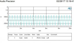
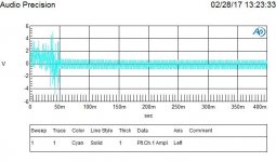
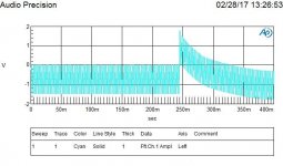
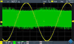
The attached are the time domain waveforms at the h-bridge output to a single tone input. I expect a peak to peak amplitude of ~1.5V at the output (swinging between +/-0.75V).With what kind of anti-aliasing filter? And what kind of decimation filter? How are they modelled?
The antialiasing filter is an active RC filter modelled with spice model of the
opamp and resistors and capacitors. The decimation filter is a cic filter. Whole of the digital filter is modelled as behavioural blocks.
What kind of simulation? Transient or small signal AC? What are the delays? What order is your digital loop filter? What is the loop gain at e.g. 50 kHz? What stability criterium you used and what were the results quantitative? The devil is in the details.
Transient ams simulation. I have tried with different orders. With any order , I face the same issue in closed loop. The loop gain s ~2dB at 50kHz. But why is 50kHz significant? I check the transient time domain waveforms to see if the system is stable.
If it is not modelled at all, then how you simulated the loop?
I model the h-bridge just as a gain block.
Why don't you share the results of your measurement showing instability?
Attachments

However we don't know if you used limiter on duty cycle control or not, and if there is a dependance of the anomaly on signal amplitude and/or freq, the supply voltages, signal voltages, load, etc...
Could you please elaborate?
Could you please elaborate?
Elaborate what? That you didn't share details?
You should elaborate the details of your project. Or at least ask specific!
Do you mean elaborate the neccessity of the limiter? It's in the datasheet on page 19:
http://www.ti.com/lit/ds/symlink/tas5103.pdf
"Use of TAS5102/3 in High-Modulation-Index Capable Systems
..."
There are many other (protection) functions in the IC. Have you considered them? Didn't any of these activated?
Do you know how many things can go wrong in such a system? 100+1! Do you really think it was possible to tell the real reason without knowing the details?
The attached are the time domain waveforms at the h-bridge output to a single tone input. I expect a peak to peak amplitude of ~1.5V at the output (swinging between +/-0.75V).
(OFF: Please care quoting!)
"Time domain"? Nothing can be seen on most of the pictures, only the amplitude. This is not a result. Nothing is visible from the waveform. Even the frequency is invisible.
This is what ClassD measurements look like:
http://www.diyaudio.com/forums/attachment.php?attachmentid=602018&stc=1&d=1488304445
http://www.diyaudio.com/forums/attachment.php?attachmentid=602019&stc=1&d=1488304445
The antialiasing filter is an active RC filter modelled with spice model of the opamp and resistors and capacitors.
Freq? Order?
The decimation filter is a cic filter. Whole of the digital filter is modelled as behavioural blocks.
Stage number? Delay? Chance of overflow in integrator?
Transient ams simulation. I have tried with different orders. With any order , I face the same issue in closed loop.
I don't understand you. Tried how? In simulation or in real life?
What's with the many other questions?
The loop gain s ~2dB at 50kHz. But why is 50kHz significant?
It is not. Every freq is significant, but you told nothing. I just tried to get some tiny bit if information from you. Actually the freq what would be interesting would be where phase drops to 0 degrees, but since you provided 0 information about phase characteristics, I can't have info about this freq.
I check the transient time domain waveforms to see if the system is stable.
I model the h-bridge just as a gain block.
It's OK. As long as you are in the linear domain for every stages.
Common mode is set by the opamp.
So there is an opamp. OK. This is a new information. But what about my question? Is common mode attenuated? Isn't OPA overloaded in common mode?
Attachments

- Status
- Not open for further replies.
- Home
- Amplifiers
- Class D
- Stability issues with a closed loop class D amp built with TAS5103