When playing with one of the amplifiers in Bob Cordell's book, I found a surprising case of instability in a double-EF output stage.
The amplifier is the example from the book, page 63. It normally uses the not too fast MJL2119x transistors. Because I saw a problem with robustness against the output series resonance at high frequencies, I tried to use the faster MJL3281/1302. To my surprise, the output stage became completely unstable, bursting into oscillation of about 8MHz during the positive half-wave. This can be seen below in instability.png. If one introduces base-stopper resistors of 10R, the circuit again is stable, whereas 2R are not enough. The quiescent current was about 50mA as in the case with MJL2119x.
Although not that extreme, I know this from experience. The sound of an amplifier may change more than reasonable, if one changes a little bit the base-stopper resistors or changes a little bit the unity gain crossover of the global NFB. For another project, I therefore decided to completely abandon darlingtons in the output stage.
One can always question the accuracy of a simulation model that does not even include stray capacities and inductances and that heavily depends on the transistor models. Nevertheless it would be nice to have a better way to evaluate the OPS stability than looking at the transient response.
After all, a multiple-EF contains a tight feedback loop around the transistors that should be accessible to analysis via Bode diagram. The three pictures show a proposal for that.
Below, ef-mjl21194.png tries to analyse the loop of the original OPS. In order to break the intrinsic feedback loop, the emitter current of Q2 is measured by R3 and translated into the original current by G1, leaving the emitter of Q2 at almost constant potential. (This even more correctly would be possible with a 0V-voltage source in place of R3 and a current-dependent current source instead of G1, depending on the current through the former voltage source)
Thus, Q1 and Q2 do not "see" the feedback signal. From 20mA to 2A output current (stepping of IE), the unity gain crossover appears to be in the region 20 to 30 MHz, phase margin is always larger than 90 degrees. (BTW, the value of R7 - VAS output resistance - has no influence at all).
The difference between ef-mjl3281.png and ef-mjl3281-10R.png is the base stopper resistor R2 in the latter. One sees lower unity gain crossover freqencies and better phase margins. Nevertheless, even the former Bode diagram would suggest stability.
Are there any proposals how to better evaluate the OPS stability and the "distance to the disaster"? I have the impression that my simple approach does fail. One point is of course that only one half of the OPS is included into the model. But in the positive half wave, the negative OPS should not contribute to the behaviour.
Does anybody have a hint how one should evaluate the intrinsic loop of multiple-EF output stages in the frequency domain?
BR,
Matze
I haver found that the VAS stage usually is the source of oscillation.
I usually put a 120pf from base to collector to limit its bandwidth.
In your circuit it looks like q6 and q10 need this capacitor.
You will need to experiment with the value to get a compromise between no oscillation and losing bandwidth too much.
I usually put a 120pf from base to collector to limit its bandwidth.
In your circuit it looks like q6 and q10 need this capacitor.
You will need to experiment with the value to get a compromise between no oscillation and losing bandwidth too much.
Matze, you should always include base stoppers in an EF. If you add a bit of inductance in the base of your drivers, you will really see them sing (say 5 to 10nH).
Another trick that works well is ferrite beads in the base, right next to the device.
I use EF3's in my designs and they are very stable - you can take a look at my site below- especially the write up on the e-Amp.
Another trick that works well is ferrite beads in the base, right next to the device.
I use EF3's in my designs and they are very stable - you can take a look at my site below- especially the write up on the e-Amp.
Small capacitors limit the BW, i see commercial brands usually limit at predriver, but we're limit at driver. Which're better? because predriver devices usually have high Ft more than drivers.
Matze, you should always include base stoppers in an EF. If you add a bit of inductance in the base of your drivers, you will really see them sing (say 5 to 10nH).
Another trick that works well is ferrite beads in the base, right next to the device.
I use EF3's in my designs and they are very stable - you can take a look at my site below- especially the write up on the e-Amp.
Bonsai,
Totally agree with adding base inductance to really bring out the problem as well as better modeling of a real circuit (somewhat surprised that the oscillation occured without adding these). Another oscillation inducing parasitic is the emitter to ground capacitance.
I'm not opposed to ferrites like some but I do put resistors across them.
I haven't figured out a better method for assessing margin (other than discrete transistor small signal model but this is very cumbersome, and not very accurate) but increasing the parasitics to well beyond practical gives a good indicator.
edit: Attached a good article by Dennis Feucht on the subject, p.s. Spice lets you enter negative resistances.
Thanks
-Antonio
Attachments
Last edited:
Only upper half wave is unstable.
I guess it is the voltage bias of the EF causes the oscillation. Voltage bias network will lose control when frequency is high enough.
Try to put an capacitor paralleling to the voltage multiplier.
See what will happen.
I guess it is the voltage bias of the EF causes the oscillation. Voltage bias network will lose control when frequency is high enough.
Try to put an capacitor paralleling to the voltage multiplier.
See what will happen.
Hi,I guess it is the voltage bias of the EF causes the oscillation. Voltage bias network will lose control when frequency is high enough.
Try to put an capacitor paralleling to the voltage multiplier.
See what will happen.
this helps. [Should have figured out that on my own 🙁.] I will give Bob a hint, maybe he can add the capacitor in his next edition.
Bonsai,Matze, you should always include base stoppers in an EF. If you add a bit of inductance in the base of your drivers, you will really see them sing (say 5 to 10nH).
Another trick that works well is ferrite beads in the base, right next to the device.
I will have a look onto your design. The question for me is: if I include e.g. 10R as base stopper or a ferrit bead, how far am I then from oscillation (comparable to: how large are the stability margins in the global NFB loop)? My experience with amplifiers is that even the smallest tendencies of instability may change the sound, at least in a high-end audiophile system.
Antonio,I haven't figured out a better method for assessing margin (other than discrete transistor small signal model but this is very cumbersome, and not very accurate) but increasing the parasitics to well beyond practical gives a good indicator.
edit: Attached a good article by Dennis Feucht on the subject, p.s. Spice lets you enter negative resistances.
thanks for the paper. It seems to be the kind of thing I was looking for.
Hi,I haver found that the VAS stage usually is the source of oscillation.
I usually put a 120pf from base to collector to limit its bandwidth.
at least in my attempt to produce the Bode diagrams, the VAS output impedance (R7 in ef-mjl21194.png) does not not have an influence at all. So even if one reduces the overall open-loop gain, this would not improve the intrinsic OPS stability.
But this is only a result of this simulation approach, and I'm not sure, whether I'm doing it right.
Thank you all and BR,
Matze
I see people use 2R2, 4R7 and 10R for base stoppers of BJT output transistors.
I think one should use at least 4R7.
Then I see people use base stoppers for the drivers, too.
Especially when using triple EF stages.
But what value I am not sure of.
I have a guess 22R or 47R are good values.
Having a capacitor 1uF or 2.2uF across VBE multiplier I have seen many.
I never understood why ... now I know why!
Thanks for an interesting topic, Matze 🙂
Regards
When playing with one of the amplifiers in Bob Cordell's book, I found a surprising case of instability in a double-EF output stage...
Are there any proposals how to better evaluate the OPS stability and the "distance to the disaster"? I have the impression that my simple approach does fail. One point is of course that only one half of the OPS is included into the model. But in the positive half wave, the negative OPS should not contribute to the behaviour.
Does anybody have a hint how one should evaluate the intrinsic loop of multiple-EF output stages in the frequency domain?
...
I recommend you look at this link to see Ovidiu's simulation. I haven't really studied it yet but looks impressively detailed and carefully analysed.
Best wishes
David.
Last edited:
Bonsai,
Totally agree with adding base inductance to really bring out the problem as well as better modeling of a real circuit (somewhat surprised that the oscillation occured without adding these). Another oscillation inducing parasitic is the emitter to ground capacitance.
I'm not opposed to ferrites like some but I do put resistors across them.
I haven't figured out a better method for assessing margin (other than discrete transistor small signal model but this is very cumbersome, and not very accurate) but increasing the parasitics to well beyond practical gives a good indicator.
edit: Attached a good article by Dennis Feucht on the subject, p.s. Spice lets you enter negative resistances.
Thanks
-Antonio
Thanks for that Antonio - I will take a look.
By the way, one other instability mechanism is with the VAS transistors themselves. This typically happens when you use a transistor with high Cob. Cob is highly dependent on the base-collector voltage. So, as your TIS stage swings from the - to the + rail, the total Miller capacitance changes significantly (NOT an issue of course with low Cob devices). This can then cause the global loop to go unstable at the top and/or bottom of the waveforms depending upon which side the TIS amplifier is - and it is especially prevelant as you come off the waveform peaks or out of clipping. It seems to be more of an issue with Lin type designs - I guess in fully balanced topologies, the total Cob of the dual TIS arrangement sort of evens things out a bit. There is no effective cure other than to use a low Cob transistor.
BTW matze, you are right that you should decouple the Vbe mulitplier - I have had instability issues with those as well.
BTW matze, you are right that you should decouple the Vbe mulitplier - I have had instability issues with those as well.
Last edited:
The Vbe multiplier is a DC voltage generator.
It should have no effect on the AC performance of the system.
But, to have NO effect on AC performance, the Vbe multiplier must have zero AC impedance between the collectors of the TIS and it's complementary sink.
A long convoluted trace between these two transistors can never have a zero AC impedance. A cap from collector to collector to minimise inductive reactance of the trace and then the Vbe added across the cap.
I would guess that PCB layout as well as the Vbe decoupling cap are almost of equal importance here.
Last edited:
I recommend you look at this link to see Ovidiu's simulation. I haven't really studied it yet but looks impressively detailed and carefully analysed.
Best wishes
David.
Hi David,
thanks a lot for the reference. This is obviously serious work, and I hopefully can learn from him.
Best regards,
Matze
Mr. Cordell deals at length with Vbe 'spreaders' and shows they become inductive at HF .. hence the need for some capacitance.The Vbe multiplier is a DC voltage generator.
It should have no effect on the AC performance of the system.
But, to have NO effect on AC performance, the Vbe multiplier must have zero AC impedance between the collectors of the TIS and it's complementary sink.
However, IMLE, huge caps have little or no effect on 1pp zillion THD within the audio band though they do have significant advantage for supersonic signals.
IMHO, huge caps across the Vbe 'spreader' are evil as they start to charge / discharge especially on overload. You are unlikely to need more than 100n and in fact less than 100p is usually sufficient to avoid oscillation. Sometimes, you find the bigger caps make the distortion residual higher order at 20kHz.
_____________________
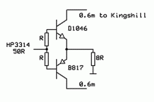
On straight Emitter Followers, here's some results from Jurassic times when I wasn't a beach bum and the design of commercial Power Amps was of serious concern.
Emitter Follower Stability Tests 16jul91
1. R = 0R5 8R load. Osc. on downward slope of +ve half
2. R = 1R5 Stops
3. R = 0R5 1u across rails Stops
4. Ccb 18p Stops
5. 100n+10R Zobel across bases. R=2x0R5
The Kingshill was a large dual regulated PSU. The moral ..
- always decouple close to the outputs/drivers with large electrolytics
- always use some base resistance and not too low a source Z
- Ccb (ala Cherry) may help but I spurn these evil inventions of the devil.
Attachments
and no bias either.No Re Richard?
Though, unlike Waly, I don't have a brain the size of a planet, I'll attempt some useful comment.
I was annoyed that a plain EF into 8R could be as unstable as a zillion device, zillion MHz ULGF amp as proposed by various gurus & pseudo gurus. The behaviour is identical to several Golden Pinnae complete amps into 'real life' speakers.
Putting unstable stages into feedback loops is unlikely to be a good recipe for overall stability.
The main evil is 2' of twisted cable to the PSU. You can sim this behaviour if you allow for the evil inductance.
Instead of Waly's equations, graphs, etc... which probably exceed my technical capabilities, I instead chose to show some simple 'real life' solutions which work. 🙂
The 4 most useful are listed. They at least allow your EF to behave as you'd expect under worst case.
Three of these,
- base resistors
- Zobel from base to base
- lossy decoupling of rails
The last, increased Ccb, will increase THD.
This test also shows that driving the o/p stage from LoZ may not always be a good thing.
BTW, the values shown are the bare minimum to stop the test case oscillating. In a real amplifier, you'd want at least 3x safety margin to ensure your O/P devices behave .. hence 4R7
The main evil is 2' of twisted cable to the PSU. You can sim this behaviour if you allow for the evil inductance.
😎🙂
The reason to put all volt regulators and PS/bypass caps right AT the circuit and not remotely. Been doing this since day-one with preamps.... same need to do it for any analog circuit; Keep that low PS Zo where it is needed. Improves regulation as well as stability.
THx-RNMarsh
Last edited:
- Status
- Not open for further replies.
- Home
- Amplifiers
- Solid State
- Stability analysis of EF output stages