My test referred to in post30 gives some back ground information to those that followed my first inquiry about the capacitance effect when the SSR is open.
That test was a lot different from the way the SSR is used to protect a speaker from a failure.
A normal speaker of 8ohms impedance fed through a 10nF capacitor will not receive damaging DC, nor will it receive damaging AC.
The roll off of the 10nF 8ohms filter is @ ~2MHz.
The load for my test (I was using the speaker to "INDICATE" whether the SSR was turning off when I applied test failure modes to the detectors) is 1k ohms. The roll off is ~16kHz. I am hearing a filter that is allowing a much higher proportion of the test signal to pass through the SSR.
The open SSR capacitance is not going to affect the way the SSR prevents damage to the attached speaker.
Ok, now I am confused. This thread started about using SSRs for line level switching. 4066 was brought up earlier. Then in #32 it was stated that 4066 wasn't good enough for this. Now stated #36 that I would be suprised how good a 4066 could be for this. Am I missing something?
I haven't explained it very well.
The 4066 type switch is not good enough to be used as a simple 'in line' switch for line level signals. In other words using it like a mechanical switch in series with the audio to be controlled. This is because the switch has significant capacitance to cause signal breakthrough when 'off', and also has a slightly non linear on resistance that varies with the signal voltage that can appear across the switch.
However, it can be very good indeed if you work around those limitations by incorporating it into a 'virtual ground' type circuit, whereby the switch never sees any significant signal voltage across it when on. When off, a second switch element is used to shunt the signal to ground before it enters the switch. This ensures a very high 'off' attenuation factor at all frequencies.
The SSM2402/SSM2412 series are analog switches designed specifically for high performance audio applications.
They are JFET swiches and should be avaialble still.... not too expensive last time I looked..
EDIT: Hmm... maybe not easily available after all... pity
They are JFET swiches and should be avaialble still.... not too expensive last time I looked..
EDIT: Hmm... maybe not easily available after all... pity
Last edited:
Now I see Mooly. You explained it ok. Being so new to this, I missed the point when you said the 4066, when used properly, can work well. I missed the "properly" part. Don't lose patience with me, I'm the student. You guys are the teachers. That "Dunce" hat fits me pretty well sometimes. A thought just came to mind. When one input source is active, the other input sources and switches will be off. So the only signal will be on the two active (left & right) switches that will be turned on. Doesn't that negate signal pass through on the off switches? .
No, it's still crosstalk. The leakage still will be summed to the output node along with the 'on' signal.
FWIW, PhotoMOS devices can work well, but they're as pricey as really nice mechanical relays, such as the Teledyne 712. So, unless there's a compelling reason to use an SSR, a 'good old relay' will often work better and will be simpler to apply.
FWIW, PhotoMOS devices can work well, but they're as pricey as really nice mechanical relays, such as the Teledyne 712. So, unless there's a compelling reason to use an SSR, a 'good old relay' will often work better and will be simpler to apply.
Well folks, I am throwing in the towel. I will never finish if I keep following this route. I will experiment with what I have already bought after I finish my pre-amp. I am ready to spin some 1960's and 70's vinyl. Two inputs and a switch. I can always modify down the road. Thanks everyone for all the help and information through this thread.
Attachments

A thought just came to mind. When one input source is active, the other input sources and switches will be off. So the only signal will be on the two active (left & right) switches that will be turned on. Doesn't that negate signal pass through on the off switches? .
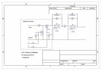
Look at this diagram and imagine the FET's are replaced by 4066 switch elements. All the inputs that are OFF all have the left hand switch turned ON and the series switch turned OFF. That shunts the incoming signal to ground as there is simply a divider action of 18k in series with Ron of the left hand switch. Even if Ron were high (say 100 ohm) then the signal has already been attenuated by around 45db. In other words for 1vrms applied to the input, only around 5.5mv rms would be across the 'shunt' switch. That 5.5mv is all that is then applied to the switch that is OFF. That is all it has to block.
The opamp - input is always at zero volts, irrespective of any signal level applied to the selected input... that's the beauty of the 'virtual earth' or inverting configuration the opamp is used under. Both inputs sit at zero volts... which can be a bit hard to grasp until you look at how the inverting opamp works.
The one input that is active see the left hand switch OFF and the right hand one as ON. Now we have 18k PLUS the Ron of the switch but because the - input is at zero volts under all conditions the right hand switch sees only the same 5.5 mv or so across it, and so does the now open shunt switch.
So in all conditions, each switch sees minimal signal voltage across it.
Attachments
I will keep on working on this, just going to stop and get my pre-amp built first. Then get back on this. Thanks for all your help Mooly.
- Status
- Not open for further replies.
- Home
- Source & Line
- Analog Line Level
- SSR switching between input/output