Sandro, I use SSR in my commercial amps. The distortion at 200 W into 8 ohms (every unit is measured as an outgoing test) is 7 ppm at 1 kHz. I can’t measure lower (QA401). The SSR is outside the FB loop.
Simulations show SSR’s typically contribute less than 1 ppm distortion.
I don’t think there is an issue with these things. Use low Rds(on) trench devices, make sure they are driven into saturation and switch them on and off quickly to keep them within the energy ratings and you have a very superior solution to an EMR.
The resistance is for the most part linear in saturation, but not so otherwise.
http://hifisonix.com/wordpress/wp-content/uploads/2012/08/Speaker-Relay-V1.03.pdf
🙂
Some time ago, I read some comments about serious application of SSR in Hi-Eng audio gear brands. I was reative of this kind of solution and prefer the conventional big contact relays.
Could you please share your schematics with us?
Attached all can find datasheets and application to Si875x
Regards to all.
Attachments
Sandro, I use SSR in my commercial amps. The distortion at 200 W into 8 ohms (every unit is measured as an outgoing test) is 7 ppm at 1 kHz. I can’t measure lower (QA401). The SSR is outside the FB loop.
Simulations show SSR’s typically contribute less than 1 ppm distortion.
I don’t think there is an issue with these things. Use low Rds(on) trench devices, make sure they are driven into saturation and switch them on and off quickly to keep them within the energy ratings and you have a very superior solution to an EMR.
The resistance is for the most part linear in saturation, but not so otherwise.
http://hifisonix.com/wordpress/wp-content/uploads/2012/08/Speaker-Relay-V1.03.pdf
🙂
I have measured the THD contribution of low RDSon MOSFETs used for SSR’s. For typical DIY Class AB amps, they don’t add distortion and in some cases, actually reduce it by a small amount (a similar effect was also noticed by tomchr). Here is the THD vs frequency for the VHEX+ Class AB amp, for 25wrms into 8ohms:
Here is THD vs power:
In both cases “yes” means with the SSR. As you can see, the lines are essentially on top of one another, and in some regions, the SSR actually is a bit less.
Thanks for link Andy.
As I was telling Damir, the main requirement to achieve linear RDS_ON is to keep VGS constant for all output voltages of the amplifier. That's it... as simple as that.
In your write up, I see you use a 12V Zener (figure 1) to create that constant VGS... that works. Also, looking at the figure, I see you put the SSR in the return line of the speaker, i.e. on the ground side and not on the output of the amp. That is very interesting, since now you don't need a fancy MOSFET driver like the SI8752 which will save you a couple of bucks.
Thanks again for the link!
Best, Sandro
I have measured the THD contribution of low RDSon MOSFETs used for SSR’s. For typical DIY Class AB amps, they don’t add distortion and in some cases, actually reduce it by a small amount (a similar effect was also noticed by tomchr). Here is the THD vs frequency for the VHEX+ Class AB amp, for 25wrms into 8ohms
It is completely dependent on the Gate drive circuit you use. The trick is to keep VGS constant vs. voltage output swing.
Do you have a schematic?
Hi Andy, is there a trade-off of having the SSR on the ground side of the speaker connection? All I see is good things since it makes the gate drive circuit so much simpler.
Just that the speaker outputs are hot when protection is operating, which might be counter-intuitive, and for a high power amp potentially a shock-hazard for the unwary.
Hi Sandro
Switching the return line does indeed save on the fancy driver, but unfortunately if you short the speaker hot lead to the chassis, you bypass it so that specific implementation is not foolproof. This is what I did in the nx-Amp - details on tne hifisonix website.
The schematics for the commercial stuff I unfortunately cannot post up but can confirm it’s microprocessor based, failsafe and switches the speaker hot line. It does use a Vishay photovoltaic driver.
All I see is good things since it makes the gate drive circuit so much simpler.
Will that work for BTL amps where there is no "ground" connection for the spealer?
If I make a gen 2 version of my SSR DC protect circuit, it will have the sensing circuit ground isolated from speaker "ground" so that BTL amps with dual live outputs can be used. It will also have a logic output to tell a SSR or mechanical relay on the mains to cut the power to the amp. This would be easy enough as both the sensing circuit and MOSFET gate drive circuits are optically isolated. For now though, the very simple circuit that is the size of two postage stamps seems to work very well.
Hi Andy, is there a trade-off of having the SSR on the ground side of the speaker connection? All I see is good things since it makes the gate drive circuit so much simpler.
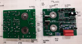
I chose to connect SSR between amp hot output and loudspeaker, and there is no need to separately connect integrated DC offset detector.
If you look at schematic and layout in first post there two more connections, LED indicating DC offset detection and TR showing in that case about 2 V that could be used to switch off the amp power supply (some switching power supplies have input for that).
My new PS regulator (cap multiplier) has switch off input.

My new PS regulator (cap multiplier) has switch off input.
Is there a link or is this under development?
Is there a link or is this under development?
Under development.
Hi Damir, do you have an .asc for the circuit in post #1?
It's here.
Attachments
Damn, I didn´t see this thread before, otherwise I might have jumped on a couple PCBs. Mady my own PCB now with PMA´s circuit, which is more basic but approved and I only wanted DC-protection anyway.
Output Relays
How I wish that all projects (approved and ideally with layouts etc.) would be in the WIKI listed in categories.
But then we wouldn´t read and search as much!
Output Relays
How I wish that all projects (approved and ideally with layouts etc.) would be in the WIKI listed in categories.
But then we wouldn´t read and search as much!
SSR relays are great for the "thd is everything" crowd only to my ears the sound is even worse than using classic relays. No idea if paralleling a few mosfets is going to make a difference.
That's some statement?
Do you have a link to the circuit you have used, where this is experience is based on? What Fet's were used? Sure the FET's were fully turned ON?
Do you have a link to the circuit you have used, where this is experience is based on? What Fet's were used? Sure the FET's were fully turned ON?
People don't like plenty of caps or resistors for no apparent technical reason. How is this different?
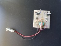
CSD19505 with Rdson 2.6mOhm. That's what i use in my sync rectifiers. Fed directly from a VOM1271 photovoltaic driver. Assuming 8v Vgs the mosfet has less than 3mOhms.
Built a couple of these to test in the speaker output and also unipolar for the PS rails. Did not like what they did to the sound in either spot. Never tested them before the large smoothing caps, but there they should be fine. One of the test jigs appears to have miraculously survived until now.
Attachments
People don't like plenty of caps or resistors for no apparent technical reason. How is this different?
CSD19505 with Rdson 2.6mOhm. That's what i use in my sync rectifiers. Fed directly from a VOM1271 photovoltaic driver. Assuming 8v Vgs the mosfet has less than 3mOhms.
Built a couple of these to test in the speaker output and also unipolar for the PS rails. Did not like what they did to the sound in either spot. Never tested them before the large smoothing caps, but there they should be fine. One of the test jigs appears to have miraculously survived until now.
You are talking here without any argument.🙁
- Home
- Amplifiers
- Solid State
- SSR for power amps