Agree that measurement is incredibly important otherwise bad things happen, however your post read as the MOST important is measurement, I feel measurements are there to check correct operation as designed and implementation is correct, however for me listening is the last word.
I am an Industrial Electrician so I know how important measurements are!
I am an Industrial Electrician so I know how important measurements are!
It's another of my guesses, but 30+30Vac seems better for +-25Vdc.
Andrew,
By my calculations if we are using 30+30Vac on the secondaries then we have approx 1.4times that after rectification i.e., about 42+42Vdc. If we generously give the reg 6V on top of its output voltage of 25V then we have a spare 11V or so which surely is not necessary. Am I missing something?
Chris
measure the voltage across the CCS to identify what difference there is with the two different transformers.
Supply each transformer from a Variac, setting the voltage fed in to the minimum specified by your supplier.
Measure again the CCS voltage. Do any of these CCS voltages give you cause for concern?
Your ears, no matter how good, and your brain, no matter how advanced, cannot match measurement information across the CCS.
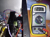
Voltage across R301:
6.3Vac trans = 1.31V
9Vac trans = 1.36V
R301 is 10ohm
The output is the same 3.3V, the different will be CCS current of 50mA.
Powering my new B3
Powering my new B3 I need to reduce the voltage to 5.25V instead 5.5V for BII but what surprise: lowered the BiB voltage to 5.25V before without any load & after connected the B3 & "voila" now only can reach 3.37Vout, the current is the same 2.37V:3R3= 718mA, don't touched the Vref remained the same as per BII "2.5-5.5Vout BJT output reg. 1 red 1.9V LED, 1K trimmer. Other parts jumper."
I suspect that isn't the same load the B2 & B3.
Of course that I can increase the trimmer value or add a small resistor in te voltage ref area what I want to know what's happen?
Attachments

Powering my new B3 I need to reduce the voltage to 5.25V instead 5.5V for BII but what surprise: lowered the BiB voltage to 5.25V before without any load & after connected the B3 & "voila" now only can reach 3.37Vout, the current is the same 2.37V:3R3= 718mA, don't touched the Vref remained the same as per BII "2.5-5.5Vout BJT output reg. 1 red 1.9V LED, 1K trimmer. Other parts jumper."
I suspect that isn't the same load the B2 & B3.
Of course that I can increase the trimmer value or add a small resistor in te voltage ref area what I want to know what's happen?
If your load is taking too much current then it is likely that you will not be able to set the voltage. You will have to do something about the current; altering the voltage ref area components without addressing the current problem will not work.
Chris
Last edited:
So
What current is your transformer providing for each secondary? 30VA
What value have you for R101? 3R3
Four LEDs green, correct? YES
What is the voltage drop across each green LED? 1.8-1.9V
What value for C105? 10.000Uf
Chris
Transformer current sufficient.
4 times 1.9V = 7.6V
Say current draw of 700mA = Vgs of about 5.5V.
7.6-5.5=2.1V
I=V/R. I=2.1/3.3. I=640mA.
Not enough current for 700mA. R101 needs to be 3ohm or lower (2.1/0.7). I don't know up to what current the BiB is designed to go.
chris
4 times 1.9V = 7.6V
Say current draw of 700mA = Vgs of about 5.5V.
7.6-5.5=2.1V
I=V/R. I=2.1/3.3. I=640mA.
Not enough current for 700mA. R101 needs to be 3ohm or lower (2.1/0.7). I don't know up to what current the BiB is designed to go.
chris
Hmm, Salas just to confirm, 1.9V = RED LEDs, yes? Because i saw other people who used the regs in the same application and they used the green LEDs in Dx02,x03,x04 instead. Is it because their current used is different?Use 3 1.9V leds and 1.2R 2W setting resistor (R101 etc.) for 0.5A available if you can't find 1.3R.
and now turn the mains supply voltage down to suppliers specified minimum. Measure again.Voltage across R301:
6.3Vac trans = 1.31V
9Vac trans = 1.36V
R301 is 10ohm
The output is the same 3.3V, the different will be CCS current of 50mA.
The fact that you have already lost 50mV tells me you are getting close to dropping out.

Hmm, Salas just to confirm, 1.9V = RED LEDs, yes? Because i saw other people who used the regs in the same application and they used the green LEDs in Dx02,x03,x04 instead. Is it because their current used is different?
Different voltage.
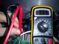
OK. After calculation errors it is about the right current levels. The drop across the LEDs depends on their current I believe to some degree.Measured voltage accross R1 2.37 V : 3R3 = 718mA
If you are supplying the right current at the reg level one has to ask if the load is drawing more than this?
Chris
OK. After calculation errors it is about the right current levels. The drop across the LEDs depends on their current I believe to some degree.
If you are supplying the right current at the reg level one has to ask if the load is drawing more than this?
Chris
Extracted from leonvb BIII manual in the TP site:
"The standard board requires an input voltage of 5.25V and it draws approximately 440mA when one is using the recommended set of Trident shunt regulators"
Looks 5ish to me, better calculate based on Vgs=5V. Also your LEDS maybe ~1.9V at the small current they will run, their spec voltage drop Vf is given at 20mA nominal usually.
From an earlier post.
Chris
- Home
- Amplifiers
- Power Supplies
- SSLV1.1 builds & fairy tales