I was hoping to get a little hand holding with building my first SSLV v1.1.
I know it is late in the game (actually seems like its over and everyone went home). Everyone seems to have the v1.3 now and etc.
I bought these boards a while ago for a phono amp, but was too intimidated by them and it was too easy to just use a battery supply instead.
I’ve re-read the pdf and looked at the spreadsheet more times than I can count. Calculations and spreadsheets are not my thing...my eyes just glaze over after a few minutes. I don’t really understand all of the fields that are being asked for.
I need to build an 8V power supply for a Shigaclone transport. I will also need to figure out power supplies for a D3 tda1541 DAC I want to build.
I’m trying to take one step at a time here.
So I’d like something that I can dial in the voltage in a range from 5V to 10V with a potentiometer. That way I can hopefully just populate additional SSLV boards I have the same way to make supplies I will need in this range.
There is info in the build PDF to help populate for 5V and 10-25V supplies, but not the range I am interested in.
I have a variety of transformers that have 12V and 15V dual secondaries that range from 50VA to 100VA.
I chose a 12V Triad VPT24-1040 and Sum R RC00509151 15V 50VA as possibilities for this supply.
I’ve gone through the BOM at the end of the build PDF and laid out what I have to try and figure things out.
I don’t know the exact current demands of the transport used in my build. It is a Sanyo unit gutted out of JVC boom box. I read in the Shigaclone build thread that it might consume about 150ma.
I am having problems with the temporary power supply solution I came up with. It is a mosfet regulator originally designed for a headphone amp that I was not using. I tried feeding several wallworts into it until I found that a 12V input gave me almost exactly the 8V the transport supposedly required.
My problem was that the transport wasn’t reading the TOC of many of my CDs. After doing some research and testing on the transport I realized that although I had 8V out of the mosfet regulator once it was loaded down by the transport circuit, that was only when it was idle.
As soon as I activated the transport to read the TOC there were a lot of fluctuations in the voltage I measured going into the circuit from the regulator and it fell all the way down to about 6V.
I have temporarily substituted a 15V wallwort and the transport will now read the TOC and play any CD I have tried in it. However, the idle voltage coming from the regulator in to the transport circuit is now at about 10.5V. It dips down to about 9V when it is reading the TOC, but I fear this voltage level may not be within manufacturer tolerances and may cause premature failure of the laser or another part of the circuit.
I think the problem may be that the regulator and wallwort I was using did not support the current demands of the circuit when it was activated to read the TOC.
I need to be able to at least try running the transport circuit at the specified 8V with a supply that can handle these demands.
I’m sorry for the long winded explanation. I’m trying to figure out not only what components to populate the SSLV properly for the voltage range I need but also whether or not using film or electrolytic capacitors will be a better choice for the circuit I am powering.
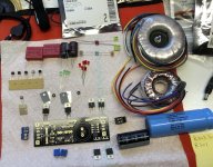
I have attached a picture of what I have been able to dig up to try and populate the SSLV for my needs.
The first cap I found for C305 in the regulator section is a 15000uF 35V. I’m not sure if this is rated high enough.
The only high voltage alternative I have in a single cap is a huge Cornell Dubilier 12000uF 80V which I got a bunch of from a surplus for amp supplies.
I have U860 for the regulator section.
I have the mini kit from Tea Bag with the other jfets, mosfets, LEDs and resistors for R302,304,306,307 and 308.
I also have WIMA MKS 10uF 100V and Elna Silmic II 220uF 50V and 47uF 35V.
I have Bourns 5K and 10K trim pots as well.
The big questions are:
Do I have to measure the GR grade K117 in the kit from Tea Bag so I install them in the low, medium and high positions mentioned in the manual?
Do I populate all four green LEDs in the D302A to D304 positions?
How should I populate the voltage reference area given my desired voltage range?
What should be the value and rating of R301?
I know it is late in the game (actually seems like its over and everyone went home). Everyone seems to have the v1.3 now and etc.
I bought these boards a while ago for a phono amp, but was too intimidated by them and it was too easy to just use a battery supply instead.
I’ve re-read the pdf and looked at the spreadsheet more times than I can count. Calculations and spreadsheets are not my thing...my eyes just glaze over after a few minutes. I don’t really understand all of the fields that are being asked for.
I need to build an 8V power supply for a Shigaclone transport. I will also need to figure out power supplies for a D3 tda1541 DAC I want to build.
I’m trying to take one step at a time here.
So I’d like something that I can dial in the voltage in a range from 5V to 10V with a potentiometer. That way I can hopefully just populate additional SSLV boards I have the same way to make supplies I will need in this range.
There is info in the build PDF to help populate for 5V and 10-25V supplies, but not the range I am interested in.
I have a variety of transformers that have 12V and 15V dual secondaries that range from 50VA to 100VA.
I chose a 12V Triad VPT24-1040 and Sum R RC00509151 15V 50VA as possibilities for this supply.
I’ve gone through the BOM at the end of the build PDF and laid out what I have to try and figure things out.
I don’t know the exact current demands of the transport used in my build. It is a Sanyo unit gutted out of JVC boom box. I read in the Shigaclone build thread that it might consume about 150ma.
I am having problems with the temporary power supply solution I came up with. It is a mosfet regulator originally designed for a headphone amp that I was not using. I tried feeding several wallworts into it until I found that a 12V input gave me almost exactly the 8V the transport supposedly required.
My problem was that the transport wasn’t reading the TOC of many of my CDs. After doing some research and testing on the transport I realized that although I had 8V out of the mosfet regulator once it was loaded down by the transport circuit, that was only when it was idle.
As soon as I activated the transport to read the TOC there were a lot of fluctuations in the voltage I measured going into the circuit from the regulator and it fell all the way down to about 6V.
I have temporarily substituted a 15V wallwort and the transport will now read the TOC and play any CD I have tried in it. However, the idle voltage coming from the regulator in to the transport circuit is now at about 10.5V. It dips down to about 9V when it is reading the TOC, but I fear this voltage level may not be within manufacturer tolerances and may cause premature failure of the laser or another part of the circuit.
I think the problem may be that the regulator and wallwort I was using did not support the current demands of the circuit when it was activated to read the TOC.
I need to be able to at least try running the transport circuit at the specified 8V with a supply that can handle these demands.
I’m sorry for the long winded explanation. I’m trying to figure out not only what components to populate the SSLV properly for the voltage range I need but also whether or not using film or electrolytic capacitors will be a better choice for the circuit I am powering.
I have attached a picture of what I have been able to dig up to try and populate the SSLV for my needs.
The first cap I found for C305 in the regulator section is a 15000uF 35V. I’m not sure if this is rated high enough.
The only high voltage alternative I have in a single cap is a huge Cornell Dubilier 12000uF 80V which I got a bunch of from a surplus for amp supplies.
I have U860 for the regulator section.
I have the mini kit from Tea Bag with the other jfets, mosfets, LEDs and resistors for R302,304,306,307 and 308.
I also have WIMA MKS 10uF 100V and Elna Silmic II 220uF 50V and 47uF 35V.
I have Bourns 5K and 10K trim pots as well.
The big questions are:
Do I have to measure the GR grade K117 in the kit from Tea Bag so I install them in the low, medium and high positions mentioned in the manual?
Do I populate all four green LEDs in the D302A to D304 positions?
How should I populate the voltage reference area given my desired voltage range?
What should be the value and rating of R301?
Attachments
The big questions are:
Do I have to measure the GR grade K117 in the kit from Tea Bag so I install them in the low, medium and high positions mentioned in the manual?
Do I populate all four green LEDs in the D302A to D304 positions?
How should I populate the voltage reference area given my desired voltage range?
What should be the value and rating of R301?
-No
-Yes
-Two red Leds & 5k trimmer. All other Vref parts positions jumper.
-12R 3-5W for ballpark 250-300mA CCS
Thanks Salas...I really appreciate the help.
Since the PDF says shoot for 5VDC over desired output with the transformer I’m going to use the Sum R 15V 50VA.
Is the 35V rating of the 15000uF cap for 305 good enough?
Should I stick to using the WIMA MKS 10uF 100V for C302 and C304 and keep the 1R at 307...as opposed to using electrolytics given the circuit I’m powering?
15V Tx might give you 19-20V rectified DC give or take. Incl. a rough losses estimation. Not best choice for Q301 dissipation if you will not exceed 10V reg output. Q305 15mF 35V is of very good smoothing capacity and the voltage rating ample even if with the 15V transformer.
Better use electrolytics at Vref and output for the kind of circuits you are going to power. Transport etc.
Better use electrolytics at Vref and output for the kind of circuits you are going to power. Transport etc.
Thanks again for the guidance.
I will try the 12V 50VA Triad since the 15V would have unnecessary additional voltage.
I read your notes about sensitive circuits like DAC and MC phonos. I wasn’t sure if that applied to a transport as well. Better to have the extra filtering and a model I can copy for those applications.
I have the Silmic II caps I mentioned in 220uF 50V and 47uF 35V that the manual specifies for C301 and C303. Again, the voltage rating is lower than called for on the 47uF, but it should be OK for this 5-10V output range.
Is there any benefit or problems with increasing the capacitance of C303?
R307 is supposed to have a jumper with lytics anyway so there wouldn’t be a Zobel to affect.
I have several values in 35V between 47uF and 1000uF. My stock in 50V is limited to the 220uF and 1000uF.
You may use more than 220uF for C301 but not too much. 470uF/35V is fine too. Does more 1/f noise filtering. For C303 you may use up to 100uF/35V. It may help instantaneous peak load demand better. If having 50V is of course no problem in both cases. Correct, R307 must be a jumper link in this case. Don't use a particularly low ESR cap for C303. Also don't waste "audio" quality electrolytics in both positions for powering a transport application IMHO.
If you will have Vout drop you probably need more peak current for TOC search function of your transport and you may decrease R301's value progressively until the current limit (CCS) it sets is sufficient for its peak load current consumption phase.
Also see a link from post#1 about how modding the output in two wire conventional mode if it will prove helpful in case of functional difficulties as a system with the transport.
Salas is enough 4700uF as AC mains filter PSU if load is 150mA & reg. CCS is set to 300mA, or it's better 10000uF?
It's answered in the manual, more than 200mA CCS needs 10.000uF, I'm sorry Salas to ask you without read better the manual guide.

BiB 1.1 is generally the darker moody one in the family. Has less OLG more loose. Asks for more standing current to flex. In some applications it can be just what you were after.
I didn't listened the Ultra. What's the sound differences?
More dynamic less moody
- Home
- Amplifiers
- Power Supplies
- SSLV1.1 builds & fairy tales