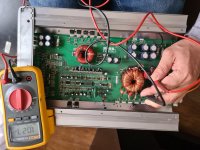
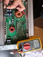
I im stucked with this amp, the PS fets was burned i checked the square signal in Gates with a scope an was ok, 4.3 volts DC, anyway i changed the PS driving transistors
i got the same square wave sinchronized,*when one is high the other is low.
My problem begins when i installed fets with p75nf75, and they got hot quickly so i tried with irf3205 with same hot results, i installed all fets but with the overheating problems i installed one fet per bank steal with overheating problem i have to clamp the fets, i detected when the fets are installed i have no signal coming from the pins 11 and 14 from the sg3525.
i can not make the PS to work, the fets are clamped so i can make a measurements, the rectifiers tha goes to the output section are out of the board with no change
this is are the voltages coming from sg2525:
with out fets in board:
1. 0.03 v
2 5.12 v
3 0.01
4 0.25
5 2.07
6 6.02
7 2.05
8 4.82
9 5.53
10 0.02
11 4.41v
12 0.000
13 10.61
14 4.41
15 10.01
16 5.10 volts
4.42 volts in gates
with fets:
1. 0.02 v
2 5.08 v
3 0.01
4 0.25
5 2.07
6 6.02
7 2.05
8 from 0.5 -- 0.8 volts
9 5.22
10 from 0.07 -- 1.07 volts
11 0.02v
12 0.000
13 from6.7---10.61 volts
14 0.04
15 from 6.54 to 10.01 volts
16 5.10 volts
i suspect the toroid transformer can have some problems
i checked diodes and zeners driving transistrors ressistance gate reistances, i removed the diode bridge thath goes to both of the 15 volts regulators.
but im lost at ths moment i can not make the sg3525 give signal in pins 11 and 14 with the fets instaled, i checked to the lm393 involved with the protection circuit an all voltages seem fine, even when the amp starts remote to positive, the red led turn on for about two seconds then the blue led turns on and the red off, the blue led stays on but dimming constantly.
Last edited:
Did you try using a loading capacitor on the gates of the PS FETs to see if the drive looked good when loaded?
Did you try twisting the transformer with the FETs in the circuit (with a current limiter) to see if the current draw changed?
Did you try twisting the transformer with the FETs in the circuit (with a current limiter) to see if the current draw changed?
i tried to twist the transformer it is firmly atached to the board, it did not move ,i aplied more stregth, the symptoms and current demanded did not changed.
i,m going to try with the caps instead of the fets with 5 nanofarads in each bank do you think is enough load?
i,m going to try with the caps instead of the fets with 5 nanofarads in each bank do you think is enough load?
load caps installed
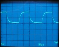
i installed a 0.022 microfarads caps for simulate load, and i get similar signal only a bit curved at the edges ,not perfectly square i post a picture.
aperently the driver transistor is capable of manage the load.
again i,m suspecting of the transformer, or what else could be 😕😕
i installed a 0.022 microfarads caps for simulate load, and i get similar signal only a bit curved at the edges ,not perfectly square i post a picture.
aperently the driver transistor is capable of manage the load.
again i,m suspecting of the transformer, or what else could be 😕😕
Attachments
Last edited:
Are you sure that the cap is 0.022uF?
Is the cap connected directly across the gate and source pads of the PS FETs?
Is the waveform from the gate pad of the loaded PS FET?
Is the cap connected directly across the gate and source pads of the PS FETs?
Is the waveform from the gate pad of the loaded PS FET?
The caps are 22 nF , they are connect between gate and source
I take the reading before te resistance of the gate, my mistake
I take the reading before te resistance of the gate, my mistake
Transformer?
If the signal is ok with load caps, I think the next Step will be check the transformer for short circuits in the copper windings.
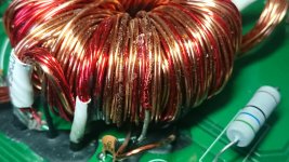
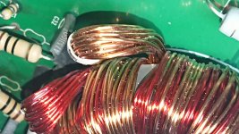
Looking at the transformer I see something suspicious
Please coment if its convenient to desoldier the transformer from the board to check it a d visual inspection
If the signal is ok with load caps, I think the next Step will be check the transformer for short circuits in the copper windings.
Looking at the transformer I see something suspicious
Please coment if its convenient to desoldier the transformer from the board to check it a d visual inspection
Attachments
Last edited:
It definitely looks bad.
If the enamel that appears burned scrapes off easily, exposing the copper, that confirms that it's bad.
The last photo shows commonly seen damage that's easy to deal with. The burned windings may require rewinding the transformer or replacing it if available from the manufacturer.
If the enamel that appears burned scrapes off easily, exposing the copper, that confirms that it's bad.
The last photo shows commonly seen damage that's easy to deal with. The burned windings may require rewinding the transformer or replacing it if available from the manufacturer.
Transformer?
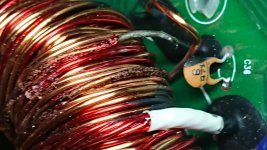
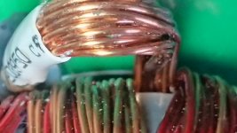
I take another picture to apreciate the last imagen again from diferent angle, and It looks normal the copper looks tha same color, apparentely the last imagen seems like overheat in the windings. But in this one looks good
I take another picture to apreciate the last imagen again from diferent angle, and It looks normal the copper looks tha same color, apparentely the last imagen seems like overheat in the windings. But in this one looks good
Attachments
Last edited:
The last image looked like there may have been a single point where the windings shorted but I don't see it in the last image you posted.
It's the other images that seemed to show a long section of wire that had overheated and delaminated.
It's the other images that seemed to show a long section of wire that had overheated and delaminated.
I understand thats why I posted the Last image, Because the 3 rd image looks like overheat the copper wire but it is not, in 99% certain that the transformer is the problem i think i m going to desoldier an inspect it.
again with this one, i maked some measurements with the multimeter, and i found some weird values, between the drain pin of the PS fets (withouth fets) and the secundary of the PS transformer (without the rectifiers brige)i found 1.08 Megaohms.(i think this value must be higher near to infinite)
Something weirdest is that i found about 1.1 megaohms between dranis PS fets and the point of rails( just after the rectifiers convert the ac voltage into dc the voltage with no rectifier installed)
Between the center pin and side pins of the rectifiers i have no resistance (with no rectifiers installed )
Only to confirm, but with this values the probability of short circuit in the ps transformer i thin are near to 100%
Thanks in avance. For your help
Attachments
What's the resistance between the primary ground and the secondary ground?
Between the input and output of the rectifier wouldn't be the transformer. The transformer only connects to the input terminals of the rectifier. The output goes to the rail caps.
Do you read the same for all rectifiers from every center leg to the outer legs?
Between the input and output of the rectifier wouldn't be the transformer. The transformer only connects to the input terminals of the rectifier. The output goes to the rail caps.
Do you read the same for all rectifiers from every center leg to the outer legs?
I can not make test at this moment,i know that between center pin and side pins must be isolated( with no rectifiers diode) side pins has alternating voltage the center has the rectified voltage(rail voltage). This voltage is the sum of both pulses of the banks, amplified by the transformer, thats why i comment that is so weird, that indicates a short circuit that i need to find
I m goin to make the test you suggest and post it
Thank you
I m goin to make the test you suggest and post it
Thank you
Between prim and sec ground i have 1.023 M ohmsWhat's the resistance between the primary ground and the secondary ground?
Between the input and output of the rectifier wouldn't be the transformer. The transformer only connects to the input terminals of the rectifier. The output goes to the rail caps.
Do you read the same for all rectifiers from every center leg to the outer legs?
I only have two rectifiers slots and the readings are the same in the 4 outer legs all reads 1.023 Mohms to primary ground and 0.2 ohms to secondary ground
Between center pin and the outer pins of the same rectifier a got 2.13 kohms variable i think because capacitors is charging but stabilizes in 20 secs, the other rectifier stabilizes in 3.7 kohms between center leg and both outer legs.
- Home
- General Interest
- Car Audio
- SSL EVO4000.1 Class d