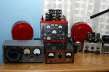
Finally had some time to finish matching speakers – the "Fire Truck Amp" project is done! 
I still have two more boards and some ideas… 🙄
I still have two more boards and some ideas… 🙄
An externally hosted image should be here but it was not working when we last tested it.
An externally hosted image should be here but it was not working when we last tested it.
An externally hosted image should be here but it was not working when we last tested it.
That is a really nice looking amp! a Variac sitting next to it supplying the AC current would compliment your SSE perfectly. At least the one I have.
Would you be so kind as to tell us the overall length width and height of the box the board and components are packaged in?
Thank you...Blake
Would you be so kind as to tell us the overall length width and height of the box the board and components are packaged in?
Thank you...Blake
The SSE board is 7.5 inches wide. You can see the 5 mounting screws on the top of the unit, so I'm guessing about 10 inches wide, 12 tall.
That is a really nice looking amp! a Variac sitting next to it supplying the AC current would compliment your SSE perfectly. At least the one I have.
Would you be so kind as to tell us the overall length width and height of the box the board and components are packaged in?
Thank you...Blake
Thanks! The enclosure measures approx 8.5" tall, 7.5" X 11" at the top and 9.75" X 11" at the bottom. It's packed pretty tightly. The front left mounting hole on the board overlaps with the rectifier tube guard so there is a bracket inside to shift it about an inch to the left.
I do have a couple of variacs with power line filters that I've built earlier. I was thinking about repainting the smaller one to match the amp but then wouldn't be the voltmeter redundant in this setup? 🙄 Maybe I'll just build another one.
An externally hosted image should be here but it was not working when we last tested it.
An externally hosted image should be here but it was not working when we last tested it.
Attachments
Really great looking build. Do you mind me asking what parts you used to make the bias adjustable and to make a b+ attenuator circuit? I'm still new to diy electronics, one of the reasons I chose tubelab for my project. Any helpful pointers would be greatly appreciated.
Sent from my SM-T810 using Tapatalk
Sent from my SM-T810 using Tapatalk


- Home
- More Vendors...
- Tubelab
- SSE - the “Man Cave” version