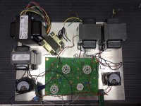
I populated this board long ago and got distracted by life. I’d like to finish it now. I’m considering layout options. I have the power transformer axis rotated 90 degrees to the OTs, as one does, but I’m wondering where I should place the choke so as to minimize hum. In the photo I have the choke with its axis aligned to the PTs and pretty close to the OT. The small anodized transformer will go underneath the chassis and I could place the choke in its place, perhaps with its axis rotated 90 to the PT.
Any advice would be appreciated.

Any advice would be appreciated.
Something I learned a lot from was putting all the transformers and inductors on a clear table and AC on the power transformer (if you use mains with a variac make absolutely sure there's no way the other windings can short and that nothing (including you ! ! ! ) can contact any of the primary or secondary terminals) and a meter across one of the other inductors and moving the metered one around to see where the highest and lowest voltages are developed.
(The right hand only rule is also good to remember here - ie. only move one inductor with your right hand and keep the left on on your lap)
It also makes a difference to cut the power and re-power as the transients can emit a stronger pulse. Doing it that way you can do the testing with a battery - just tapping one wire against terminal to create the pulses.
Some of the old Telefunken tuners I've seen had the transformers and chokes packed in tight against each other yet had no noise or hum, and in a forum conversation I remember one more experienced fellow saying that they were designed in the days when big companies like that could afford to have a bunch of engineers in the lab trying different combinations until they got what they wanted.
You can also see what happens if you put a choke directly under or over the power transformer oriented both in parallel or at 90º. You get a very clear picture of how the interaction changes with orientation and with distance.
In some circuits , with specific parts, it can work well to mount one unit on one side of the plate and another with the right orientation directly under it on the other side.
Hope this is useful
That was indeed useful and quite instructive. Thanks for the suggestion.
Choke placement in either location was acceptable when the choke was oriented at 90 degrees to the OT.
Located in sufficiently in front of the power transformer either orientation was good so long as the axis didn’t intersect the OT location.
I‘m wondering if coupling between the PT and the choke is something I should be concerned with? When the choke and PT axis align, they couple strongly. That seems like trouble.
Also, it’s surprising the jolt a big choke can deliver with a humble 1.5 volt battery!
Response in bits and pieces.
"When the choke and PT axis align, they couple strongly. That seems like trouble."
Do they cancel strongly in any rotational position? My first reaction is that if they couple strongly it's possible they could be oriented to reject strongly , but in a working circuit that would depend entirely on what field each one is generating.
"Also, it’s surprising the jolt a big choke can deliver with a humble 1.5 volt battery!"
Yeah, that really impressed me too.
In terms of the amp though, it's only a one way interaction. The other body will also be doing something so it's possible they can be oriented to each other in a way to cancel fields.
It also depends on where the choke is in the circuit. An input filter choke will generate a much larger AC field than a choke that follows a filter section, and not all parts' sensitivity to stray fields is the same.
The usual 90º orientation rule works a lot of the time but you can often see people using Lundahl iron (for example) just lining them up side by side and it doesn't seem to cause problems.
I don't have the experience to be sure what is going to happen so I always do a breadboard first.