I am building a Tubelab SSE, my first build.
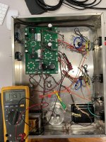
I am wiring as per image attached, with cathode feedback not used.

With the multimeter I try to read the ohms across R17 and R27. The meter swings up and down, not giving me a quick precise reading, like if a capacitor is connected in series.
If I do remove the two jumpers from T2-SEC and T3-SEC, then I can quickly read the correct ohm rating across R17 and R27.
Is this intended behavior?
I would like to point out I am using at R17 and R27 two 750ohms potentiometer in series with a 300ohms resistor, so that I can regulate the value of each R17 and R27 between 300ohms and 1050ohms, to possibly change the bias depending on the power tube used.
Thank you!
I am wiring as per image attached, with cathode feedback not used.
With the multimeter I try to read the ohms across R17 and R27. The meter swings up and down, not giving me a quick precise reading, like if a capacitor is connected in series.
If I do remove the two jumpers from T2-SEC and T3-SEC, then I can quickly read the correct ohm rating across R17 and R27.
Is this intended behavior?
I would like to point out I am using at R17 and R27 two 750ohms potentiometer in series with a 300ohms resistor, so that I can regulate the value of each R17 and R27 between 300ohms and 1050ohms, to possibly change the bias depending on the power tube used.
Thank you!
Here a video of the multimeter not being able to read the resistor value TubeLab SSE Cathode Bias Resistor - YouTube
If wired correctly there should be a cathode resistor in parallel with the cathode bypass capacitor. It is normal for a meter to read nearly shorted when first connected, then rise to the actual value of the cathode resistor.
In your case the meter starts out low then rises. The up and down readings seen are due to the meter automatically changing ranges. Lock the meter on the 2000 ohm range to make this measurement.
Your still picture shows a reading of nearly 15K ohms indicating that something in the resistance path is open circuit and you are measuring only the capacitor.
Either there is a wiring error, the pot or 300 ohm resistor is open, or not the value you think it is. Measure each part individually to verify its value.
The preferred way to do adjustable cathode bias is not a resistor and a pot in series. If the circuit goes open (the likely case here) the cathode voltage will rise to a level that tries to cut the tube completely off. If that voltage is higher than the voltage rating of the bypass cap, the cap may fail, and sometimes leak or explode.
I use a fixed resistor of about 1000 ohms in the board, then use a switch, or a pot with a resistor in series, placed in parallel with the on board resistor so that an open circuit condition in the cathode is not likely. The resistor in series with the pot is a safety resistor to ensure that you can't accidentally set the current to high.
The total resistance in the cathode circuit should go no lower than 450 to 500 ohms or so for most of the typical audio tubes. I think that 450 ohms got me over 100 mA of current with EH KT88 tubes. This made the total amp current about 230 mA which made my power transformer very HOT.
Make sense! I will order parts so to have the pot with a resistor in series, placed in parallel with the on board resistor!