Have worked on many amps thru the years but nothing completely from scratch. Due to time constraints need some quick, specific help:
Bought and assembled this amp- company about useless for English communication and help. Have a great chassis already but need to know what else besides some pots etc is needed (transformer etc).. Will be pushing a great pair of 4 ohm speakers. M1-MOS FET 120W+120W 2SK1058 2SJ62 Amplifier kit WLX I already have a completely unmarked huge transformer from a Yaqin VK-2100 (pics attached), but can not get any info on it at all. The schematics are in the link.
REALLY need some expert help trying to complete this project.
Attachments

Last edited:
I already have a completely unmarked huge transformer from a Yaqin VK-2100
The Yaqin transformer gives +/- 44VDC from a full wave bridge rectifier with a pair of 10,000uF caps.
The schematic is here: https://sc01.alicdn.com/kf/HTB17n8CJVXXXXcSXXXXq6xXFXXXh/200349805/HTB17n8CJVXXXXcSXXXXq6xXFXXXh.jpg
The M1 schematic specifies 30VAC-0-30VAC, which gives about +/- 42VDC, so pretty close.
However, the M1 also needs another winding of 0-14VAC for the protector UPC1237 circuit.
You could use a second transformer, or else derive the needed 20VDC from the main 44VDC supply.
The M1 schematic is here: http://www.ebay.com/itm/M1-MOS-FET-...d-board-70W-70W-omron-Relay-DIY-/251478690953
Last edited:
 Please don't bump! (post deleted)
REALLY need some expert help trying to complete this project.
What else do you need to know?
Thanks for trying and the PM's Ray- but I'm right back where I started. Don't know how to proceed to completion..
We would like to help you but what exactly are you asking?
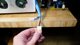
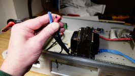
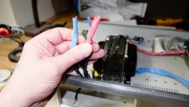
Looking at the diagrams, Im guessing those black cables with the Red and Blue shrink tubing ends and Brown and Blue leads inside (from your picture it likes like Blue and Brown in red shrink tubing and Blue and Brown in Blue shrink tubing) are the 33v AC secondaries. My other guess is the the Blue cable with the White and Black wires and 2 Blue wires are the 6.3v, 250v and 14v secondaries.
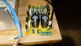
These are all guesses and clues. Were you the one who cut these wires? You still have the chassis in front of you, you cant tell where they go? The wires that were cut from the power switch would be the primaries. In the picture you can see the blue cable with the white plug going to the circuit board with fuses and rectifiers. These are the secondaries
Looking at the diagrams, Im guessing those black cables with the Red and Blue shrink tubing ends and Brown and Blue leads inside (from your picture it likes like Blue and Brown in red shrink tubing and Blue and Brown in Blue shrink tubing) are the 33v AC secondaries. My other guess is the the Blue cable with the White and Black wires and 2 Blue wires are the 6.3v, 250v and 14v secondaries.
These are all guesses and clues. Were you the one who cut these wires? You still have the chassis in front of you, you cant tell where they go? The wires that were cut from the power switch would be the primaries. In the picture you can see the blue cable with the white plug going to the circuit board with fuses and rectifiers. These are the secondaries
An externally hosted image should be here but it was not working when we last tested it.
windows 7 screenshot
Last edited:
Great pic. Was trying to determine IF the transformer would work with the M1 amp pcb I assembled and exactly how to wire it vs having to obtain a toroidal transformer. No wires have been cut from the VK-2100 power switch and remains stock. Had other questions too like how I would add a decent ALPS volume pot, etc.
If the primaries are still connected to the chassis and power switch the easiest thing to do is to power up the transformer and carefully measure the voltage coming out of the secondaries. Do it very carefully because there is a pair of wires spec at 250v ac (for tubes that you won't be using) another pair @ 6.3v AC (for tube heaters that you won't be using as well) another set @ 14v ac (possibly for speaker protection circuit) and the main set you will be needing that is 33v ac.
Btw this transformer will work with the M1. you need to rectify the 33v secondaries with filtering caps (follow the VK-2100 schematic)
Oh never mind about the rectifying and filter caps I see it already on the M1 board. After you confirm the the voltage of the secondaries just attach 33-0-33 to the M1 and the 0-14v secondaries to the protection side and it should work. Don't forget a heat sink or you will fry those output transistors
Last edited:
Ive got a huge heatshink Im going to use that I will have to tap and die the transistor screw threads, but Im not that far yet. The kit left out 2x C2705 and 2x A1145 transistors Im still trying to source CONUS.
OK- measuring vac on the one side of the transformer; the 4 wire molex with the two cream colored on the outside and the two black on the inside I get:
+ on the cream colored and - on the black 123.5vac.
But if I switch the - to the other black inside wire I get 36.4 vac.
Switching the + to the other cream colored wire and - to the other inside black wire I get 66.3vac.
Its confusing to me.
Measuring the other side of the transformer;
Blue heatshrink:
+ to the blue wire and - to the brown wire 1.8vac and .07~.01vdc
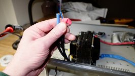
Red heatshrink:
+ to the blue wire and - to the brown wire 15.05vac and .07~.01vdc
Confusing to me as well...
OK- measuring vac on the one side of the transformer; the 4 wire molex with the two cream colored on the outside and the two black on the inside I get:
+ on the cream colored and - on the black 123.5vac.
But if I switch the - to the other black inside wire I get 36.4 vac.
Switching the + to the other cream colored wire and - to the other inside black wire I get 66.3vac.
Its confusing to me.
Measuring the other side of the transformer;
Blue heatshrink:
+ to the blue wire and - to the brown wire 1.8vac and .07~.01vdc
Red heatshrink:
+ to the blue wire and - to the brown wire 15.05vac and .07~.01vdc
Confusing to me as well...
If the primaries are still connected to the chassis and power switch the easiest thing to do is to power up the transformer and carefully measure the voltage coming out of the secondaries. Do it very carefully because there is a pair of wires spec at 250v ac (for tubes that you won't be using) another pair @ 6.3v AC (for tube heaters that you won't be using as well) another set @ 14v ac (possibly for speaker protection circuit) and the main set you will be needing that is 33v ac.
Btw this transformer will work with the M1. you need to rectify the 33v secondaries with filtering caps (follow the VK-2100 schematic)
Oh never mind about the rectifying and filter caps I see it already on the M1 board. After you confirm the the voltage of the secondaries just attach 33-0-33 to the M1 and the 0-14v secondaries to the protection side and it should work. Don't forget a heat sink or you will fry those output transistors
Oh also the two blue wires on the molex on the right side (same harness as the 4 wire molex) I get 7 vac, Went to the 6.3v input on the VK-2100 board.
I have a feeling one of the black wires on the 4 plug molex is the center tap wire for the 7 vac. So you should get 3.5-0-3.5 if you measure from each blue wire on the 2 wire molex to one of the black wires. The other black wire on the 4 wire molex is the center tap for the 33 vac. Take the Cream and Black wires that measured 36.4 vac and take a measurement from that black wire to the other cream wire and it should also be 36.4 vac. If you measure both cream wires it should be 72.8 vac. The 15.05 vac is for the protection circuit. I dont know how to explain the 1.8 vac wires, maybe they are the high voltage 250 vac secondary that is probably dead? Which explains why the amp was scrapped.
Last edited:
Yep! That all checks out. Except for rechecking the red heatshrink with the blue-brown wires on the other side of the transformer that you think is for the protection circuit; depending on which + or - lead from the DMM I get either 15.05 vac or about 7 vac.. VK-2100 is mine new from about 11 years ago. 'Scrapped' the board as would not hold the dc offset and the adjustment pots were shot and the transistors blown. Weird deal. The 1.8 vac blue heatshrink wires I dont think shows the transformer is defective. Think it would be hard to kill this one. Its massive. So.. how do I proceed? I still cant figure the outs to the speakers from the M1 pcb and there are only 2 holes by the 10000uf 63v lytics that are just marked out1 and out2. The lower right side of the pcb has markings for rin and lin and common ground hole in the middle for my chassis rca inputs. Also do not know how to add a decent volume pot. Sorry to jump around and ahead but this whole board etc is confusing.. I don't have a preamp for volume to test this, once you step me thru how to now wire it..
Try taking a reading from the Brown to Brown and Blue to Blue.
I cant really confirm where the Speaker outputs are located, I hope someone else can chime in.
I cant really confirm where the Speaker outputs are located, I hope someone else can chime in.
Try taking a reading from the Brown to Brown and Blue to Blue.
I cant really confirm where the Speaker outputs are located, I hope someone else can chime in.
All the experts in here and seems I cant get a few to simply help me wire this.. apo- on the right side of the transformer; cream and black wires that checked out, how can I attach those to the M1?
here my suggestion...
1. buy new trafo, better to buy a toroid
2. using huge heat sink and tap to die with transistor as tight as you can
1. buy new trafo, better to buy a toroid
2. using huge heat sink and tap to die with transistor as tight as you can
All the experts in here and seems I cant get a few to simply help me wire this.. apo- on the right side of the transformer; cream and black wires that checked out, how can I attach those to the M1?
To connect the 2 Cream and Black wires. On the M1 PCB these wires will go to the Green Terminal Black with 3 connections. The corresponding black wire goes in the middle and the Cream wires on each side of the black wire.
To connect the 2 Cream and Black wires. On the M1 PCB these wires will go to the Green Terminal Black with 3 connections. The corresponding black wire goes in the middle and the Cream wires on each side of the black wire.
Gotcha thats common. Guess what I am asking is Ive got two black wires for the the center. Measured them together with each of the cream wires and about 36~37 vac as in 36-0-36. So Im going with that (connecting both black wires not just one).
You mentioned the blue and brown wires with the red heatshrink on it on the opposite side of the transformer for the protection circuit. It measures 15 vac. Best I can see on the schematic is a 12v requirement. Thats the remaining 2 connections on the green terminal block. Can you confirm that on the schematic?
Reason Im asking is on the same harness as the cream and black wires is the two blues wires that only measure 7 vac. Thats not enough (or should be used) for the protection circuit. Again that was for the 6.3 vac in on the old VK-2100 board. I assume leaving these two blue wires and the other blue heatshrink wires on the other side not connected to anything is OK and will nor harm the transformer or anything when in use ?!?
Still waiting on the missing transistors before I can complete and test it. But STILL dont know how to add an ALPS pot for volume and Im still trying to figure out the fuzzy schematic for the speaker outs...
- Status
- Not open for further replies.
- Home
- Amplifiers
- Solid State
- SS kit build help