So I'm working on a design for a bass preamp pedal (hopefully running off of 9v, but maybe 12 or 18 if necessary). Right now I have a decent overdrive channel and I'm trying to mix it with a clean signal with separate volumes for the clean and overdrive. Only, I'm having issues getting a clean sound loud enough to match the overdrive. I tried a single CE amp stage which wasn't quite clean enough (maybe I needed a higher power source) and I've tried a few different op-amp layouts, to no avail.
Any guidance here would be great. According to MultiSim, I'm getting about 30db of gain before the EQ section (which of course doesn't exactly account for compression due to distortion).
So I would think a standard inverting amplifier with a voltage gain of at least 20 should get me pretty close. However, everything I tried seems to go into saturation well before then (even if I adjust the source to 18v) or simply isn't loud enough.
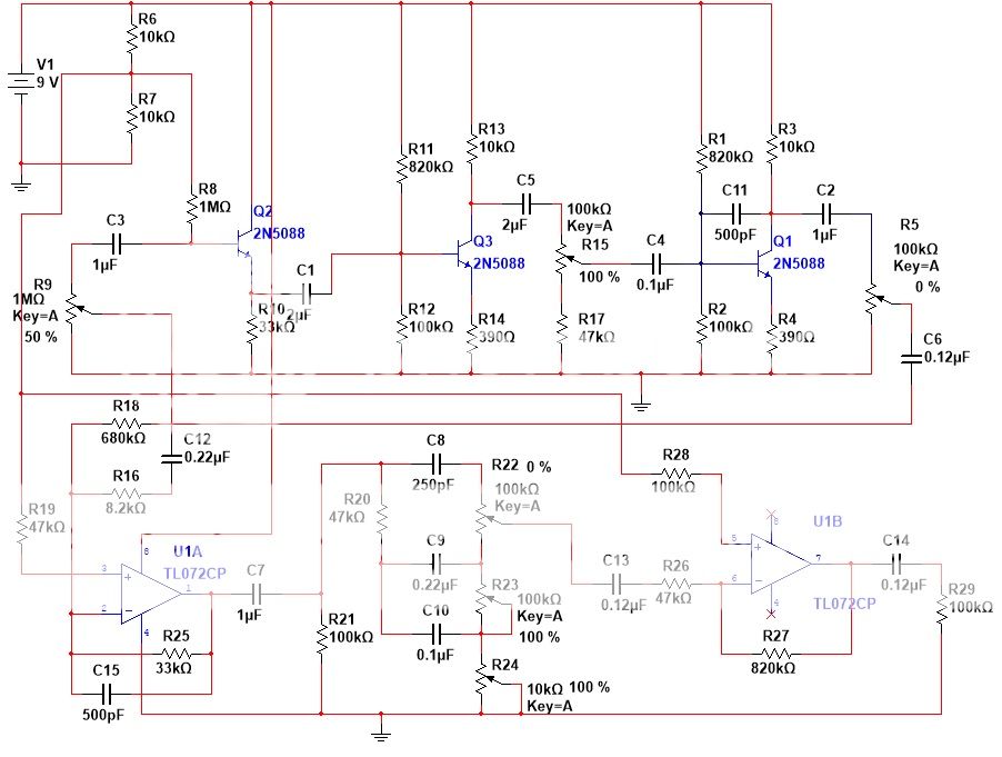
Any ideas what I might be doing wrong? My biases are almost exactly center (4.5v or 9v when I'm at 18v Vcc). Here's what I have so far. This is the overdrive and EQ sections.
Any guidance here would be great. According to MultiSim, I'm getting about 30db of gain before the EQ section (which of course doesn't exactly account for compression due to distortion).
So I would think a standard inverting amplifier with a voltage gain of at least 20 should get me pretty close. However, everything I tried seems to go into saturation well before then (even if I adjust the source to 18v) or simply isn't loud enough.
Any ideas what I might be doing wrong? My biases are almost exactly center (4.5v or 9v when I'm at 18v Vcc). Here's what I have so far. This is the overdrive and EQ sections.
An externally hosted image should be here but it was not working when we last tested it.
Hi,
Attenuate the overdrive when mixing it back with clean.
It is inevitably going to be louder than clean.
rgds, sreten.
Attenuate the overdrive when mixing it back with clean.
It is inevitably going to be louder than clean.
rgds, sreten.
Last edited:
I was thinking about doing that. I will need to amplify the resulting signal though, to get it up to line level (and give the pedal some headroom). Maybe I'll use a dual op-amp as a unity gain summing amp and a moderate gain stage.Hi,
Attenuate the overdrive when mixing it back with clean.
It is inevitably going to be louder than clean.
rgds, sreten.
Well, I implemented the summing amp and it worked well for balancing the two signals, however, I'm still only able to get a few hundred mV at the output before the op-amp is in saturation.
I take that back, it's not going into saturation. It doesn't matter how much gain there is. There is actually a constant fuzz. I tried swapping out with the other op-amps I have (the TL072 was the original, I also tried RC4558, LF412, and NE5532) and the distortion was effectively the same.Well, I implemented the summing amp and it worked well for balancing the two signals, however, I'm still only able to get a few hundred mV at the output before the op-amp is in saturation.
I am at a loss here. What are some different issues I should look into? Could it be a biasing issue? Could it be due to the fact that I am still on a breadboard and I am getting some induction from nearby loops?
I basically put together a textbook inverting single-supply summing amplifier and my output is far below the rail voltage.
Hi Guys
The divider for the half-voltage should be lower values and should have a cap to ground from the midpoint. This will keep the reference at AC ground as it should be and reduce interaction of the stages using it.
Measure the amplitude of the distorted sound, then of the clean sound. If you retain the opamp mixer it inherently has the ability to reduce the level for the distorted signal and boost that of the clean one.
Alternatively, using passive means it is simple enough to have a pan between clean and dirty with a series R on the dirty side to limit how loud that will be. The output of the pan control can be boosted by a clean running stage.
The schematic is a bit difficult to follow. It should have a clear INPUT and OUTPUT and show the separation of the clean and dirty sounds. As it is it looks like there is only one signal path.
Have fun
Yeah so far I have a decent inverting summing op-amp for the mixer. Rin is 1k for the clean and 1M for the distorted and Rf is 4.7k. This leads into a passive tone stack and then to an op-amp recovery stage. I got these two op-amps to introduce almost no distortion. Right now I'm having issues with the following stage which is intended to boost the signal to line level for the balanced line out. This is where I'm struggling. I thought a simple inverting op-amp with a gain of 10 would be easy to implement but it's giving me some trouble.Measure the amplitude of the distorted sound, then of the clean sound. If you retain the opamp mixer it inherently has the ability to reduce the level for the distorted signal and boost that of the clean one.
Yeah that was a previous design for the distortion and EQ. The bottom row is not applicable now. The output of the distortion is taken from that second CE stage (the one with NFB) and it leads into the summing amplifier.The schematic is a bit difficult to follow. It should have a clear INPUT and OUTPUT and show the separation of the clean and dirty sounds. As it is it looks like there is only one signal path.
Yeah as I was trying different things I lowered those to 10k. Should I go even smaller? I'll be sure to add that cap as well. I'm running off of a battery for the time being. Maybe I should switch to an AC adapter just to keep the voltage constant.The divider for the half-voltage should be lower values and should have a cap to ground from the midpoint. This will keep the reference at AC ground as it should be and reduce interaction of the stages using it.
If I can find some time I will draw up a complete schematic of what I have so far. My simulation software only allows 50 components so I'll have to draw it up by hand or something.
- Status
- Not open for further replies.
- Home
- Live Sound
- Instruments and Amps
- SS Bass Preamp Pedal - Some Questions