I recently had the pleasure of hearing a friend's vintage audio system which I really enjoyed. It's nothing fancy, but I loved the tube sound.
After a lot of reading here and elsewhere, I have learned that the "tubiness" comes from second-order harmonics.
I'm not at the stage where I'm comfortable working with high voltages, plus my budget is limited so good transformers are off the menu. So my question is this - is it feasible to simulate this 2nd-order distortion with solid state technology? I've seen a few mentions that JFETs can be used, but all the designs I've found so far have been for guitars (overdrive, fuzz, specific guitar amp emulation etc).
I also encountered this: https://www.crowdsupply.com/analog-artistry/leo-vintage-analog-sound , but from what I see in the limited technical information available this is effectively just EQ. I may very well look into this, but at a later stage.
Does anyone have a circuit I could try? And is it possible to have an adjustable distortion level ?
?
I do understand that this is the opposite of hi-fi, and essentially amounts to an effects box. But I thought it could be fun. Ideally this will be something I could put between source and amplifier with an on/off switch 😀
After a lot of reading here and elsewhere, I have learned that the "tubiness" comes from second-order harmonics.
I'm not at the stage where I'm comfortable working with high voltages, plus my budget is limited so good transformers are off the menu. So my question is this - is it feasible to simulate this 2nd-order distortion with solid state technology? I've seen a few mentions that JFETs can be used, but all the designs I've found so far have been for guitars (overdrive, fuzz, specific guitar amp emulation etc).
I also encountered this: https://www.crowdsupply.com/analog-artistry/leo-vintage-analog-sound , but from what I see in the limited technical information available this is effectively just EQ. I may very well look into this, but at a later stage.
Does anyone have a circuit I could try? And is it possible to have an adjustable distortion level
? I do understand that this is the opposite of hi-fi, and essentially amounts to an effects box. But I thought it could be fun. Ideally this will be something I could put between source and amplifier with an on/off switch 😀
Last edited:
You have just opened a can of worms. 
Tube sound does not come from 2nd harmonics in the opinion and experience of many people, so you are likely to get a lot of argument about that. If you are a little handy with software, there are wav editors out there that will allow you to add distortion to an audio file. You'll find if that works for you or not, before you build something.
Tube sound does not come from 2nd harmonics in the opinion and experience of many people, so you are likely to get a lot of argument about that. If you are a little handy with software, there are wav editors out there that will allow you to add distortion to an audio file. You'll find if that works for you or not, before you build something.
Uh ohhh...You have just opened a can of worms.
I've tried a few audio playback plugins, and I do like what they do 🙂
That's good. If you find one or more that you like, you may be able to imitate that sound in hardware.
Do you remember what they were?
Do you remember what they were?
My favorite so far is the Tube Saturator from WaveArts. The SPL TwinTube plugin is also really nice.
The adjustability of both is fantastic.
The adjustability of both is fantastic.
Perhaps inserting a soft clipping circuit somewhere in the gain stages Soft Clipping will emulate the tube curves well enough without resorting to software defined music.
Just an idea.
Just an idea.
The FirstWatt F3 is mainly second harmonic, very nice sounding amplifier. http://www.firstwatt.com/pdf/prod_f3_man.pdf
I don't know how many have been built by DIYAUDIO enthusiasts, but I sold around 100 LU1014D power JFETs.
I don't know how many have been built by DIYAUDIO enthusiasts, but I sold around 100 LU1014D power JFETs.
Much less in need since my last DAC/amp combo, but I've been tempted a lot to try this: A Harmonic Restorer. OK, it is still tubes, but no Xformers... and you can use for example two small leftover transformers with secondaries interconnected to get about the right supply voltage. Beside two standard tubes, nothing fancy. Keep us informed about your progress!
Best for adding even harmonics is
204 Aural Exciter | Aphex
Yes, it's not Hi-Fi, but many studios using it, and we listen it in our pure Hi-Fi amplifiers with 0.0000001 or less THD.
All FM stations use some type of exciters, so we hear this effect almost every day...
Sounds nice, I agree.
204 Aural Exciter | Aphex
Yes, it's not Hi-Fi, but many studios using it, and we listen it in our pure Hi-Fi amplifiers with 0.0000001 or less THD.
All FM stations use some type of exciters, so we hear this effect almost every day...
Sounds nice, I agree.
There are some DIY projects about this, but I did not try it.
Solid state, so no tubes and high voltages, looks DIY friendly.
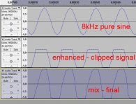
Distorted, clipped signal is mixed with original signal.
But, as I researched through net, clipped signal must be asymmetrically clipped to have even harmonics...
One of schematics:
http://www.harpamps.com/schematics/harmswtn.pdf
Solid state, so no tubes and high voltages, looks DIY friendly.
Distorted, clipped signal is mixed with original signal.
But, as I researched through net, clipped signal must be asymmetrically clipped to have even harmonics...
One of schematics:
http://www.harpamps.com/schematics/harmswtn.pdf
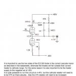
This buffer is what the late Allen Wright called a Super Linear Cathode Follower (SLCF) and I believe he got it from an early very high end Tektronics tube scope.
I built one as one off an output buffer for my Lightspeed Attenuator to drive low input impedance power amps <30kohm.
I must say it's the best tube buffer I've heard, none of that tube tubbiness, clean clear and dynamic, and not much colouration.
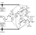
I built the original (1st pic) not the improved (2nd pic).
Cheers George
I built one as one off an output buffer for my Lightspeed Attenuator to drive low input impedance power amps <30kohm.
I must say it's the best tube buffer I've heard, none of that tube tubbiness, clean clear and dynamic, and not much colouration.
I built the original (1st pic) not the improved (2nd pic).
Cheers George
Attachments
After a lot of reading here and elsewhere, I have learned that the "tubiness" comes from second-order harmonics.
Its a popular myth but I for one don't believe it.
I'm not at the stage where I'm comfortable working with high voltages, plus my budget is limited so good transformers are off the menu.
Transformers can be hand-wound and don't need to be at all expensive (in materials that is). Sure they do take a bit of time, but this is DIY audio.
So my question is this - is it feasible to simulate this 2nd-order distortion with solid state technology?
It might be wise to check your premise. If tube sound is down to 2nd harmonic distortion, this can also be created with solid state. Just build everything single-ended classA and avoid opamps and NFB. But the reality is, with most music intermodulation distortion swamps any harmonic distortion - 2nd harmonic distortion shows up only on test tones.
Member
Joined 2009
Paid Member
... none of that tube tubbiness, clean clear and dynamic, and not much colouration...
then it's completely useless for the OP then isn't it
then it's completely useless for the OP then isn't it
Only to those who want to use tubes without much of the colourations.
Cheers George
Thanks for the responses guys 🙂.
I'll give nironiro's Harmonic Sweetener a try, as well as ragwire's ESP suggestion.
I'll report back after some solderin'...
I'll give nironiro's Harmonic Sweetener a try, as well as ragwire's ESP suggestion.
I'll report back after some solderin'...
@nironiro - a couple of questions if I may?
What is the purpose of the 10k potentiometer in the schematic (the one drawn, not the modification options)?
The pin numbers don't match the data sheet - do all the op amps use their inverting inputs, or should I go by pin numbers rather?
Thanks a ton!
What is the purpose of the 10k potentiometer in the schematic (the one drawn, not the modification options)?
The pin numbers don't match the data sheet - do all the op amps use their inverting inputs, or should I go by pin numbers rather?
Thanks a ton!
The purpose of the 10k pot is to mix how much clipped signal will be in the output.
Some kind of effect level control.
Didn't check pin numbers on opamps yet, I'm just like you still searching through net for something like harmonic enhancer, in DIY of course.
As I found, there are two "lines":
- first is original signal
- second is high pass filter, usually around 3kHz, than clipping circuit which generate distortions - asymmetrical for even order harmonics
and than those two lines are summed to output.
One more schematics from net, this looks more interesting, because it makes asymmetrical clipping, (one diode), but, as the first one, I did not try it yet.
http://experimentalistsanonymous.co...apanese Electronics Book/harmonic-exciter.gif
And yes, abraxalito is right, "tubiness" is very popular myth on the net last years, and if you make normal, properly engineered tube buffer or preamp, you'll don't hear any distortions.
Last edited:
Just for the record: it is said that the “tube sound” comes from enhanced 2ND order harmonic distortion, but this is a convenient ruse, which obfuscates what is really going on.
In a nutshell, the ideal (not for musicality, but theoretically) amplifier would offer this:
Voutput = Vinput • gain
And that's that. A straight, linear, ideal 'curve'. Because semiconductor amplifiers have long been designed to adhere to this relationship, their “distortion” figures are oft bandied about at arbitrarily low values: 0.01%. 0.003%. 0.00027% and so on. They are - if you're looking for straight, crisp idealism - as close to ideal as one might reasonably imagine. But their doppelgänger is the vacuum valve amplifier.
Vacuum tubes are weird devices (and I mean that, lovingly) in that they “kind of, sort of” are linear when used in some circuits in special ways. In truth, they're pretty nonlinear, and are actually rather “polynomial” in transfer function. A triode, for instance, might be grossly modeled as:
I = gain • V²
on the grid. (this is a really large approximation, and the power isn't really a square, but it is definitely a power, and not a linear straight line!). But the gain part of that equation is also dependent on the VA-K or voltage difference between cathode (emitter side) and anode (collector side) of the device. The larger the VA-K, the larger the nominal gain.
Well, in real world circuits using inexpensive and pretty darn linear devices like resistors, to load the anode (to convert amperes to volts, thus “amplification”), as the tube's transconductance (multiplying grid voltage into anode current) amplifies the input signal, there's a phase reversal as far as the plate is concerned (a drop in voltage at the plate with increased grid voltage).
This antiphase plate signal is a kind of negative feedback which serves to linearize the tube's power-law conduction. Got that? Its true. So, our little triode that kind-of-sort-of followed
Current = transconductance gain • Vgrid²
Becomes
Voutput = gain • Vgrid≈1.0-1.3
And the world is a happy place. Thing is … the power isn't exactly 1.0. The absolutely linear and ideal straight gain line … is still curved.
It is the curvature of that gain line which distorts the output signal to not be a simple scaled version of the input. This is important for assessing the “tube sound”.
MOREOVER, tube circuits, like all amplifier circuits, have an output range beyond which they are physically incapable of achieving. This is called “clipping”. Transistor-type amplifiers tend to be school-straight ruler amplifiers until they reach clipping, then just STOP. Sounds terrible. Like someone popping little firecrackers (its the Year of the Monkey!) during a concert.
TUBE amplifiers however, either though intrinsic nature or intentional engineering, almost always have a much broader shelf of “clipping” and nonlinearity leading to their saturation levels. Moreover, the nonlinearity is often asymmetric about the polarity axis, meaning that positive excursions and negative excursions will have quite different clipping levels, waveforms and recovery modes. This - when deliberately engineered in - is what contributes to much of the wicked “scream” of legendary solo-guitar amplifiers when mercilessly overdriven. The power supplies are intentionally underrated, so as to enhance time-varying distortion and odd recovery. And yes… there is a certain unmistakable fingerprint of musicality to it too.
SO… getting back to the leading paragraphs … the only “harmonic” component to the distortion of tube amplifiers is related to the distortions to waveforms that happen when only considering sinusoidal input signals. The “harmonicity” is something which is a mathematical consequence of distorting sinusoidal waveforms. Can be analyzed with Fourier transforms ("spectrum analyzers") and so on. Engineers love 'em. But oddly enough, in the real world, the input signals are far, far, far from being idealized sinusoids.
So what then is the “warm tube sound”? It is the hard-to-define shape of the nonlinear amplification curve of an amplifier. And yes … if one is intending to “simulate” the warm tube sound, it is really as simple as having a voltage-and-time varying nonlinearity curve applied to the signal.
But that takes more than an undergraduate degree to come to grips with.
GoatGuy
- Status
- Not open for further replies.
- Home
- Source & Line
- Analog Line Level
- SS analog warmth / tube sound circuit wanted