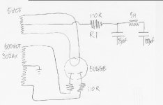
I'm scratching my head over some of this 2a3 ps. I've got all the voltages I want having made some minor changes since the last time I built this circuit(adding limiters to the 5u4g anodes)....but....
R1 is getting very hot, far to hot to touch...and the 302ax is also getting uncomfortable after a couple of hours.......
back to R1(its actually 110R=3x330R 10w in parallel)...its got 13vdc across it, which I make to be 118ma and 1.53watts...well I wasn't expecting it to get hot
looking further R1 has also got 15vac across it but I'm not sure of the significance of this.
question is, should it(R1) be getting toasty hot??
The last time I built this 2a3 using a 302ax I used 6sn7 instead of 6sl7 and the tx was as cool as a cucumber after hours of working......I can't find any significant difference but I've either cocked up somewhere(have looked and looked) or this 302ax is not the same beast as the last 302ax....or, anybody got any other suggestions......
2a3 heaters are running at 2.5vac exactly
6sl7 heaters are running at 7vac give or take...they are lifted by 80v
Attachments
Hey,
Actually the dissipation in R1 can be shown to be: P(R1,tot) = P(R1,DC) + P(R1,AC)
where P(R1,DC) = VDC^2 / R and
P(R1, AC) = VACrms^2 / R
So I think you only calculated the first part (DC).
Also I think it is very weird that you would only get 15VAC over R1, since it is right after the rectifier. It should rather be something with 3 digits...
thanks kavermei
I had omitted the ac component...I make it 3.57 watts if the ac figure is correct.
I have little experience of resistor temperatures but the 3x10w resistors do seem to get very hot. Perhaps that is the correct temperature for 3.57 watts out of 3 x 10watt resistors...or maybe I have a dodgy DMM..I will check again.
A watt is a watt, regardless of the resistor's power rating and 4W is nothing to sneeze at. How much DC current does your amp draw from the top of the last filter cap?
hi rknize
a watt is indeed a watt, I'm just not sure what 3.5 of them should feel like spread over 3x 10 watt resistors.
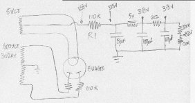
below are actual readings so to answer your question(I hope) 2ma for the srpp(on top of 47uf) which leaves 116ma(on top of 100uf) for the 2A3s.
Ed
a watt is indeed a watt, I'm just not sure what 3.5 of them should feel like spread over 3x 10 watt resistors.
below are actual readings so to answer your question(I hope) 2ma for the srpp(on top of 47uf) which leaves 116ma(on top of 100uf) for the 2A3s.
Ed
Attachments
That 338V measurement is going to be sketchy because that is not really DC there nor is it a nice AC sine wave that a multimeter is likely to be able to measure accurately. If you empirically knew the current draw on the 318V tap (measured directly), then we could add it to the 2mA SRPP plus 1mA or so and we would know the total draw through R1.
ok...well how about doing it the otherway round?
there are 2 x 6sl7 srpp, bottom cathode at 1.6v on 2k2 = 0.75ma x 2 = 1.5ma
there are 2 x 2a3 cathode at 44v on 750R = 58ma x 2 = 116ma
total 117.5ma
this is pretty close to the 118ma which is 13 volts dropped across R1(110R) so I didn't think the 338 - 325 was too far out.....
the voltage across R1 measures 13vdc
with respect to ground : before R1 = 338 and after = 325
everything seems to tally, what am I missing?
edit: ahhh the ac component which is lost in the choke??
Last edited:
It all adds up in my head, but that doesn't mean anything. 🙂 There is an AC component, but if you look at it in terms of Mr. Thevenin, the currents all have to add up. Even though the instantaneous currents through R1 may be very high when the diode is conducting, it is nearly zero when the diode is off. When looked at in terms of power dissipation, it all averages out, no?
It's pulsating DC...
Russ is correct
You can use PSUD2 to figure out what should be happening. There is only voltage across the resistor when current flows. This is during the charging peaks of the input capacitor (8uF). Your DVM may or may not tell you the whole story because it's pulsating DC, not a sine wave. In this case your DVM is not too far off in showing you something like 15 volts which looks reasonable based on the waveform. I don't think adding up the AC and DC measurements from the DVM gives you a meaningful answer here. You need the true RMS value of the waveform to calculate power.
It's a little surprising that 3 10W resistors would get hot with only a few watts but maybe your resistors are rated for 10W but physically small or located where there is little ventilation?
Cheers,
Michael
PS When I have more than a watt or 2 to dissipate, I usually use a heatsinked resistor (the gold ones or a TO220/TO247 case)
Attachments

Last edited:
- Status
- Not open for further replies.
- Home
- Amplifiers
- Tubes / Valves
- srpp 2a3 power supply