The thing is that companies and thier brands have become a commodity of sorts, changing owners frequently.
And add quarterly statements, the tendency is to increase profit.
Also, like I have said in other posts, gradually the out sourcing contractor is made responsible for the entire product in a box, and squeezed for price...in desperation, the contractor will also cut costs.
Most consumer electronics are made in the Far East, with production of labor intensive items shifting out of large Chinese cities to the hinterland, or places like Vietnam.
In a situation where the part must last just past the warranty stage, and the managers in charge may have shifted to other places, with this 'achievement' of cost cutting in their resumes, just bear with it.
Replace with the best quality parts, and enjoy the music.
And if needed, build your own.
Hi Dan,
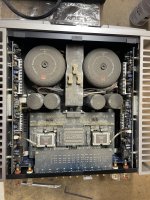
I just received an M3 from my neighbor who bought it new. It recently sent up a smoke signal and now the left channel does not work. I pulled the top cover other than it being very dusty (I have since blew it out) there is no obvious signs of a problem in the components that I could see, I suspect that there may be something under the line driver amp as that is the only place I cannot see.
The AMP turns on but goes into "Protect Mode" after a few seconds of being on. Would really like to know what you have found with your M3 and any tips on disassembly.
Regards,
Dan
Had a very quick look at the circuit. Would definitely take out the muting transistor and corresponding parts and if really necessary, replace it with a miniature relay. Won't put any good money in fancy caps, not here. The servo opamp certainly affects the sound and will replace it with a suitable fet input device that i already like for its sound. Not certain what the circuit around Q355/356 does, perhaps soft clipping. Will try to understand it better and remove it. The zeners at the output too. May consider replacing the 1.2k feedback resistors as those are certainly audible.
Last edited:
@analog_sa, I will need a little help understanding your suggestion, if possible could you point out the components in a reference drawing or better yet picture?
Thank you
Thank you
Welcome to the forum!
I've attached a service manual found on the web.
I strongly urge that you repair the amp back to its original working state before you think about "improvements." In other words, don't try to fix it by improving it--- you're likely to get hopelessly lost in a morass of unknown original damage vs. unproven modifications, with no way to separate the two.
I surmise you feel comfortable repairing the unit and know how to keep yourself safe? You have equipment, tools, and some experience?
Start by trying to locate the damage. Was there literal smoke? Is there any audio delivered in the moments before protection asserts? I would look at power supply voltages and for DC at the amp output at L302 in front of the relay.
Keep us posted. Good luck!
Attachments
Thanks you @BSST appreciate the manual an guidance and agree I want to get the M3 up and running to enjoy it, plus I got if for free.
I do feel comfortable replacing components and have repaired a few audio components in the past (with instruction) I don't have the theoretical experience and few diagnostic skills.
I do feel comfortable replacing components and have repaired a few audio components in the past (with instruction) I don't have the theoretical experience and few diagnostic skills.
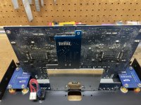
I figured out how to safely dissemble the amp, taking the back of first and removing all screw's from the IEC power connector.
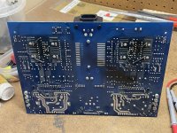
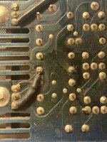
I took pictures but could not see anything obvious that has failed (specifically on the left channel) except the highlighted resistors on both sides that have their outer coating flaking off off.
Any recommendations based on experience as to what components might have failed that I can check?
@saabracer23
.JPG")
I took pictures but could not see anything obvious that has failed (specifically on the left channel) except the highlighted resistors on both sides that have their outer coating flaking off off.
Any recommendations based on experience as to what components might have failed that I can check?
@saabracer23
Attachments
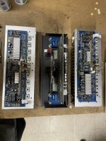
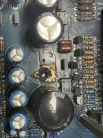
Those resistors you've noted look suspicious to me. They appear to be associated with the 71V regulators. Are the voltages correct? The reference for those regulators are 20V regulators. In short, are all supplies correct?
I would next check DC voltages at the amp outputs. That's quickest insight to the problem area.
I would next check DC voltages at the amp outputs. That's quickest insight to the problem area.
I don't particularly like this amp but I'm sad to see its internal state.
Some devices don't have an easy life...
Some devices don't have an easy life...
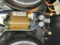
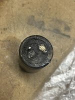
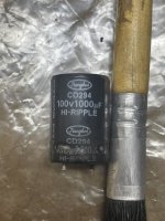
After further disassembly I found the blown capacitor that was the source of the smoke. My plan of attack is to check all of the transistors and the diodes, to create a list of failed parts to order I will then replace the components (in pairs).
Have you seen this before and shed and light on the cause or have any advise on a diagnostic procedure to see if there are any other upstream components that would cause the capacitor and resistors to fail?
Have you seen this before and shed and light on the cause or have any advise on a diagnostic procedure to see if there are any other upstream components that would cause the capacitor and resistors to fail?
Attachments
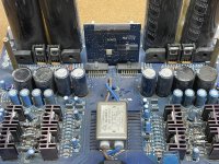
You've probably already considered, but have you pondered what may have led to the capacitor failure? Was it spontaneous failure, or perhaps collateral damage arising from a failed power supply rectifier?
Good luck!
Good luck!
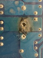
Which cap failed, i.e. what's its Reference Designation (Ref Des) in the schematic? I can look to see if anything obvious jumps out. Failed power transistors are possibilities, but that's a rabbit hole to be avoided if possible. Which resistors have failed? They may be casualties of transistor failure.
The board looks like it took some damage but the traces on the back do not appear to affected, is there something I can put on the top side of the board to "re-coat" the copper substrate?
Attachments
I also finished checking the voltage drop across all of the diodes and there are several at 0.54 volts. D607 is at 0.405V and D91 is at 4343 V.
I repaired the board and sourced parts. One of the transistors Q711 tested bad and I order the part based on the schematic 2SC2240. When I removed the transistor it had a different part number C1775, these are much harder to find.
Would it be ok if I used the 2SC2240 in it's place to test or should I replace all of the C1775s or just source replacement C1775?
Would it be ok if I used the 2SC2240 in it's place to test or should I replace all of the C1775s or just source replacement C1775?
- Home
- Amplifiers
- Solid State
- Squeezing the most performance from NAD M3 as I can, switching to different outputs, is it worth it?