Is your feedback connected?
Yes it's the black shielded cable off of speaker terminal
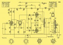
Just a thought, Check you schematic and your work. But It looks like there's two jumpers missing in you feedback and bias circuit for the EF86. here's a pic of a couple of ideas. I haven't gone over most of the rest of the circuit, But maybe this will help.
An externally hosted image should be here but it was not working when we last tested it.
Take a look at this part of your print and your wiring to make sure it's correct. red circles mark what I'm talking about
An externally hosted image should be here but it was not working when we last tested it.
So I finally got the parts for the snubber network and had the time to install them and they did not help.
So I was checking my voltages again and realised that the power tubes are well beyond max dissipation.
Plate voltage - 420v to ground
cathode voltage - 44v to ground
The cathode resistors used are 470R so:
44 / 470 = 94mA
.094 x 376 = 35.2
yes I know this include the screen but still way to high.
I think I remember reading somewhere on here about an UL linear power amp having stability problems because the power tubes were being pushed too hard but I couldn't find it. I didn't see any red plating but I am going to go ahead and try some 560R cathode resistors which means more waiting.
Has anyone run into this before? Or maybe I just got a bad OPT?
While I am waiting for the resistors to get delivered is it possible to bias the power tubes colder with a 9v battery for testing. I was thinking of running the positive to ground and the negative to a cap and to the grids. It should take me down to 35v on the cathodes which is where they should be.
I have never done hybrid fixed/cathode bias before but don't see why not, I just wanted to run it by the forum before I blow something up.
I have never done hybrid fixed/cathode bias before but don't see why not, I just wanted to run it by the forum before I blow something up.
Mixed bias is fine. However, a high cathode voltage could be caused by the oscillation.
You need to acquire an oscilloscope. Without this you are flying blind. We don't know whether you have the typical UL transformer parasitic (just above the audio band) or some RF parasitic which could be at many MHz.
You need to acquire an oscilloscope. Without this you are flying blind. We don't know whether you have the typical UL transformer parasitic (just above the audio band) or some RF parasitic which could be at many MHz.
Famousmockingbird how good is the voltmeter you are using to measure the 1.5v on the output? I doubt a voltmeter can measure radio waves. I wonder if the screech you hear is not going from low frequency to high frequency...could your amp be motorboating? Have you followed that schematic exactly? What are the cap values in your power supply??
The values I went with on the power supply are:
C15 - 50uf reservoir cap
C12 - 100uf OPT center tap
C5 - 50uf PI node
C4 - 50uf EF86 node
All other cap values are the same.
The voltmeter I have is a Fluke true rms meter, it cost me like $150 a few years back. I don't think the meter is reading the real AC voltage at the speaker out because for only 1.5vac the dummy load was getting hot fast.
I would love to get my hands on an oscilloscope but I don't know anybody that has one, I am really the only person I know that does this for a hobby.
I know an oscilloscope is an important tool for this hobby and I have been looking into buying one but unfortunately it won't be soon. For now I am going to tinker in my spare time with the layout and such, maybe add a cap from plate to plate on the PI.
The upside is I have some really cool looking paper weights now.
Attachments
update!!!!!!!!!!!!
Before when I ran the amp with preamp tubes pulled I got an awful squeal, now I don't so I think the RC snubbers are working. Also with preamp tubes pulled the power tube bias comes down to normal and I get zero voltage across the dummy load.
This means the issue is in the preamp stages.
I will try a bigger value and see if that helps. I think i have 330pf and 1000pf.
Before when I ran the amp with preamp tubes pulled I got an awful squeal, now I don't so I think the RC snubbers are working. Also with preamp tubes pulled the power tube bias comes down to normal and I get zero voltage across the dummy load.
This means the issue is in the preamp stages.
Famousmockingbird;
What value Cap did you use in your Amp for the stabilizing net work on the plate of the EF86? 47pf is very low unless you transformer is of very high quality!!! You may need more like 470pf and 4.7K. I am going by the circuit Junk Audio posted.
Phil
I will try a bigger value and see if that helps. I think i have 330pf and 1000pf.
I apologise for posting so much guys but I installed the 1000pf cap for the stabilizer network on the plate of the EF86 and so far so good.
Thank you everyone for you wisdom and especially mult for his suggestion on increasing that cap value. Now that I think about it every time I have seen this type of circuit it's usually a value of 10,000pf.
Good catch multi I really appreciate.
Thank you everyone for you wisdom and especially mult for his suggestion on increasing that cap value. Now that I think about it every time I have seen this type of circuit it's usually a value of 10,000pf.
Good catch multi I really appreciate.
You could have accidentally made a circuit with a feedback loop which is only conditionally stable. This means that it is stable under normal conditions, but if the loop gain is reduced (e.g. when shutting down) it becomes unstable. This may seem counter-intuitive but it really can happen if there is too much phase shift in the loop.
Anoher possibility is local (probably capacitive) feedback within the early stages making them unstable but they are being stabilised via the output stage and global negative feedback. When the output stage gain drops the stabilisation reduces.
You may feel I am clutching at straws. You would be right. You really need a scope - you can build an amp without one, but you can't debug without one.
Guitar amps are much cruder. Little or no global feedback. Heavily slugged forward gain. DC voltmeter is about the only test equipment needed.
My concern with the fix is that it is probably killing the open loop bandwidth, I'd be surprised if the amp currently makes 20kHz closed loop.
My experience with caps in the C9 location is that with most output transformers they cause HF instability. I've never been able to get a 5-20 amp stable with that capacitor in place. What is the value of R13, and what tap is it connected to?
The EF86 is often operated in current starved regimen where it's transconductance is significantly increased over normal operating conditions, I am wondering if something like this is happening when the amplifier initially is powered down.. Increased gain would cause the sort of symptoms encountered.
It's unfortunate that you do not have scope, it would be incredibly helpful in understanding what is going on.
- Status
- This old topic is closed. If you want to reopen this topic, contact a moderator using the "Report Post" button.
- Home
- Amplifiers
- Tubes / Valves
- Squeal on shutdown