Hey guys, I am currently trying to learn about amplifiers and I am now testing a bunch of small amps, like chip amps such as opamps and so forth. I also made a 3 transistor amp and when I put the output into my scope, I'm seeing an erratic square wave. I was under the impression that it should be closer to a sine wave since it's oscillating or AC. Am I wrong?
Thanks,
John
Thanks,
John
I'm seeing an erratic square wave. I was under the impression that it should be closer to a
sine wave since it's oscillating or AC.
it may be clipping on one or both peaks. See if the limits are at the power supply voltage
Where should I measure for the limits?
Also, I am experimenting with an lm386 amplifier, a transistor amplifier, and the ipod I'm using as the source unit is louder than the amp I made in both cases! Am I just cursed?! I am following everything to the letter.
https://i2.wp.com/www.circuitbasics.com/wp-content/uploads/2015/04/LM386-Audio-amplifier-with-Bass-Boost-NEW-2.png
I tried making this one. It's so low I can barely hear it!
Where should I measure for the limits? I am experimenting with an lm386 amplifier, a transistor
amplifier, and the ipod I'm using as the source unit is louder than the amp I made in both cases!
Not cursed, just a beginner, which can be the same thing at times.
Can you post the actual schematic diagram to help. Carefully compare
your actual circuit to the diagram that you used, there may be a mistake.
Set the scope inputs to DC coupling. Connect the scope ground to the negative battery terminal.
Now probe the output before the coupling capacitor, and also at the positive 9V terminal.
Compare them, the clipping is likely at 9V and/or ground.
Last edited:
Thank you for your response. As it turns out, I accidentally put a 10K resistor where a 10 ohm resistor should have been. It rocks now! I just wish I could get this other amp working. . . https://www.allaboutcircuits.com/projects/how-to-build-a-class-d-power-amplifier/
I bought all the extra parts I needed, the rest I had in my parts drawers and the inductor I wound myself. This one is tough though. . . Anyone have experience with something like this?
Also, about the lm386, I am wondering how it works. I'm putting in a DC signal with my 9V battery, right? And the LM386 turns it into AC for the speaker? I have been studying amps hardcore for the last 5 days. It's not easy to understand. I know my basics, what AC and DC is, I've been into electronics for the last 5 years solid. But amplifiers are new to me. Also, when I try to take readings with my DMM, I do not get any negative voltage in AC or DC. Any help is greatly appreciated.
Thanks a lot
Last edited:
An amplifier like your LM386 runs on a 9 volt battery......
It goes something like this:
In order to get the speaker cone to move in and out we must first ensure that no DC voltage is presented to the speaker. That is done by the capacitor that will be in series with the speaker.
So far so good 🙂
The LM386 now has to be biased so that its output is at approximately one of the supply voltage. Why so ? Because doing that allows the output to move both up (toward 9 volts) and down (toward zero).
So we have available a maximum swing of +4.5 volts and - 4.5 volts.
Applying that to the speaker via the coupling cap allows the speaker cone to move in response to the AC voltage and ignore the DC voltage.
A meter doesn't show any polarity for AC because it is assumed that the voltage measured is a sine that spends equal time above and below a notional zero point.
The Class D amp in your link wouldn't be a first choice to learn with tbh. Class D requires a whole new skill set regarding physical layout and correctly implementing a build.
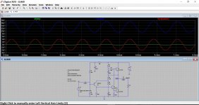
Look at the three voltages from this amp and see how the output coupling capacitor removes the DC voltage from getting to the speaker. Also notice how the amplifier output (blue) is biased to this 'half supply' voltage so that it can swing equally up and down.
It goes something like this:
In order to get the speaker cone to move in and out we must first ensure that no DC voltage is presented to the speaker. That is done by the capacitor that will be in series with the speaker.
So far so good 🙂
The LM386 now has to be biased so that its output is at approximately one of the supply voltage. Why so ? Because doing that allows the output to move both up (toward 9 volts) and down (toward zero).
So we have available a maximum swing of +4.5 volts and - 4.5 volts.
Applying that to the speaker via the coupling cap allows the speaker cone to move in response to the AC voltage and ignore the DC voltage.
A meter doesn't show any polarity for AC because it is assumed that the voltage measured is a sine that spends equal time above and below a notional zero point.
The Class D amp in your link wouldn't be a first choice to learn with tbh. Class D requires a whole new skill set regarding physical layout and correctly implementing a build.
Look at the three voltages from this amp and see how the output coupling capacitor removes the DC voltage from getting to the speaker. Also notice how the amplifier output (blue) is biased to this 'half supply' voltage so that it can swing equally up and down.
Attachments

Thank you very much for all that info. It's still foggy to me, I'm just not getting it as far as the signals are concerned and that is the most important part to understand. When I put it on my scope, I just get some ugly messed up looking square waves. I even made sure I had a perfect square on the test terminal before I connect to my signal.
What would you suggest for a beginner, I'd like to make something that has some decent power.
Thanks
What would you suggest for a beginner, I'd like to make something that has some decent power.
Thanks
Excellent teacher, Karl‼
Thanks 🙂
Thank you very much for all that info. It's still foggy to me, I'm just not getting it as far as the signals are concerned and that is the most important part to understand. When I put it on my scope, I just get some ugly messed up looking square waves. I even made sure I had a perfect square on the test terminal before I connect to my signal.
What would you suggest for a beginner, I'd like to make something that has some decent power.
Thanks
Squarewave testing is very hard on amplifiers (hard as in they sometimes don't like it).
For the LM386 you need to apply just a small signal to the input so as not overload things. I would also replace the speaker with a resistor for this kind of testing. Perhaps a 22ohm 1 watt. The LM386 is really just for portable radios and that kind of thing.
A more powerful chip amp would be a good place to start.
Have you seen this ?
The Decibel Dungeon Gainclone index page with links to all chip amp articles.
I wasn't TRYING to get a square wave, it just made it! Anyway, I just did it again and there is now 3 waves like on the pic that you posted Mooly. So that is correct, right? 2 are straight lines and 1 is a normal audio signal steep sine. The straight lines go up and down.
Would any of you happen to know if I can use an LM555 timer in place of an LMC555cn timer? I bought the parts for this amp so I'm going to attempt it.
The original LM555 has been around since the 1970's, the LMC version is a low power CMOS version.
At a basic level they are interchangeable, however the old LM555 generates a large current spike everytime it switches and so needs a good quality 47uF or 100uF connected directly across pins 1 and 8.
That said, I wouldn't like to give any assurance that the old version would be 100% a straight swap for this. You will need to confirm that the triangular output voltage is correct and meets the specification for the amp.
Thanks very much for the input Mooly, I ordered the cmos version anyway. I don't want to take chances, it's just one more potential bug I can get rid of. Thanks. . .
#1 > I am following everything to the letter.
#5 > ...a 10K resistor where a 10 ohm resistor should have been
This happens a LOT when we begin wiring stuff up. So much of electronics is outside our everyday experience. Much of it is not obvious to the eye.
Example: if you wanted a 10 pound barbecue meat, you just might question a 10K (10,000 pound) lump of meat, maybe wonder if there is some mistake. But a 10r and a 10K resistor look JUST alike, except one thin color band.
No offense, but until you have more working projects, nobody believes you "did everything right!" IME, about half the time it IS something not according to plan: wrong connection, way-wrong value. It may be deep inside, or it can be "obvious" like getting the IN and OUT jacks mixed.
> I wasn't TRYING to get a square wave, it just made it!
ALL interesting waves turn SQUARE when they slam against the inevitable limits of the amplifier. Signal is too big. Like a sexy new car 7 foot wide, driven into a garage door 6 foot wide: the sexy side-curves smashed flat. Buy narrower car. Use smaller signal.
> I'm putting in a DC signal with my 9V battery, right? And the LM386 turns it into AC for the speaker?
Actually perceptive.
The situation is that we have a weak but interesting electric signal, say from a microphone. We want a big electric signal, say for a loudspeaker. That will not happen by magic. However we have batteries, a source of large but boring power. And by 1910 we had electrically variable resistors (amplifier tubes). We put the weak/interesting signal in one circuit. We put the powerful/boring battery through another circuit. If we are clever enough, with good choices of values, we can extract a larger interesting signal.
Many advanced audio thinkers overlook the fact that the battery (or line-power supply) IS an "input". They may be forgiven because the general goal in audio design is to take the power without taking any crap that comes with it. (Not much from battery, but hum/buzz from wall-power sources.)
- Status
- Not open for further replies.
- Home
- General Interest
- Everything Else
- Square wave on opamp?