I mocked up a simple mute switch by putting an SPST on/off switch in-line with the signal on one channel between my preamp and power amp. It worked perfectly, no pop or hum or leak.
When I google for mute switch implementations though, there are all much more complicated than this. I'm sure that's not just engineers wanting to overcomplicate things, so I must be missing something. What flaw is not yet apparent to me in my simple on/off switch implementation?
When I google for mute switch implementations though, there are all much more complicated than this. I'm sure that's not just engineers wanting to overcomplicate things, so I must be missing something. What flaw is not yet apparent to me in my simple on/off switch implementation?
That arrangement could cause some kind of noise, coupling capacitor pops, hum pickup, etc.
even though you don't have any. Normally the signal would have a series resistor, which is then
shorted to ground for muting. The muting switch would typically be inside the preamp or amp,
not in-line between them, to have less chance of noise pickup. But if it works the way you want, it's fine.
Sometimes muting is done with a time delay upon power up, to mute turn-on noises.
With some preamps or other sources, especially tube circuits, this is very important.
Check with a scope and see.
I'm just messing around experimentally right now, ultimately I'd move it into the preamp.The muting switch would typically be inside the preamp or amp,
not in-line between them, to have less chance of noise pickup. But if it works the way you want, it's fine.
So, I got lucky with this particularly source/preamp/amp combination, basically?That arrangement could cause some kind of noise, coupling capacitor pops, hum pickup, etc.
even though you don't have any.
So the series resistor would go before the switch, thus being inline under both normal operation and mute operation? Or would the resistor go after the switch between the switch and ground to compensate for the missing load? What is the purpose of this resistor, exactly?Normally the signal would have a series resistor, which is then
shorted to ground for muting.
Lucky, maybe.So, I got lucky with this particularly source/preamp/amp combination, basically?
So the series resistor would go before the switch, thus being inline under both normal operation and mute operation? Or would the resistor go after the switch between the switch and ground to compensate for the missing load? What is the purpose of this resistor, exactly?
Yes, the resistor (1k or so) goes before the switch, to avoid shorting the source when muted.
Usually the switch would short hot to ground, rather than opening the wire which could cause hum pickup.
Right, ok. So, because I'm not shorting the source with my switch, that isn't needed. But, if my switch shorted the line to ground, I would need the resistor to prevent the short.Lucky, maybe.
Yes, the resistor (1k or so) goes before the switch, to avoid shorting the source when muted.
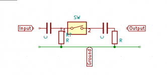
So, this would be a DC offset that exists in the circuit "naturally", not something that is created by the presence of the switch. But, when the switch is introduced it causes a pop when the circuit is closed. So, if I'm not experiencing a pop, its likely because my source->preamp->amp circuit doesn't have much DC offset?It is usual to eliminate any DC offset both sides of the switch. Half a volt floating on one side only can cause a pop, something like my drawing. But not essential.
In your diagram, what's the purpose of the capacitor/resistor pair on the output side of the switch?
They are there to block any DC offset from the device it connects to. Belt and braces really so not essential. (I should have drawn the resistor on the switch and capacitor feeds the output, same as the input side).Right, ok. So, because I'm not shorting the source with my switch, that isn't needed. But, if my switch shorted the line to ground, I would need the resistor to prevent the short.
So, this would be a DC offset that exists in the circuit "naturally", not something that is created by the presence of the switch. But, when the switch is introduced it causes a pop when the circuit is closed. So, if I'm not experiencing a pop, its likely because my source->preamp->amp circuit doesn't have much DC offset?
In your diagram, what's the purpose of the capacitor/resistor pair on the output side of the switch?
They are there to block any DC offset from the device it connects to. Belt and braces really so not essential. (I should have drawn the resistor on the switch and capacitor feeds the output, same as the input side).
Ok, so the capacitor is there to block DC, acting as a high-pass filter for all frequencies > f where f > 0. The bigger the capacitor, the lower f is, and the more fundamental signal comes through. Now, obviously, there isn't any practical difference between filtering out 1 Hz, 0.1 Hz, and 0.01 Hz, but is there any real upper bound to the value of the capacitor? Or is it simply "Pick something big enough that f ~= 0 and isn't stupid expensive and physically massive"?
EDIT: If the formula for -3DB frequency = 1/2PiCR, I can achieve the same results with a small value for C and a big value for R. A high value film cap gets expensive, but high value resisters are cheap. Is there a tradeoff to using a 1kR vs 10kR vs 100kR etc resistor value?
This is to do with switching a live signal - any abrupt switching introduces a click unless the waveform just happens toWhen I google for mute switch implementations though, there are all much more complicated than this. I'm sure that's not just engineers wanting to overcomplicate things, so I must be missing something. What flaw is not yet apparent to me in my simple on/off switch implementation?
be zero-crossing at that moment (unlikely). For instance if a bass tone is present the switch will generate a transient (step)
with components all the way across the audio band to 20kHz and beyond, which is very audible (just like a scratch on a record).
In professional audio mixers used for mastering a recording this is simply not good enough for a drop-in or punch-in switch, so
soft switching would be implemented which is basically a very fast fade-in or fade-out, on the order of a few ms (slow enough
to lose the click, but still orders of magnitude faster than sliding a fader control).
In home audio the click-free switching property is more of a luxury than a necessity of course - that could be viewed as over-
engineered (some will disagree though
")
This is to do with switching a live signal - any abrupt switching introduces a click unless the waveform just happens to
be zero-crossing at that moment (unlikely). For instance if a bass tone is present the switch will generate a transient (step)
with components all the way across the audio band to 20kHz and beyond, which is very audible (just like a scratch on a record).
In professional audio mixers used for mastering a recording this is simply not good enough for a drop-in or punch-in switch, so
soft switching would be implemented which is basically a very fast fade-in or fade-out, on the order of a few ms (slow enough
to lose the click, but still orders of magnitude faster than sliding a fader control).
In home audio the click-free switching property is more of a luxury than a necessity of course - that could be viewed as over-
engineered (some will disagree though
Thank you for this explanation, I appreciate it. May I pick your brain about appropriate values for the C and R in the mute circuit?
Does the relative size of R and C to achieve that 0.01 matter? Could R be huge and C be tiny, or vice versa?Which mute circuit - lots of ways to do this. As I said the time-constant would be somewhere around 10ms probably,
so RC = 0.01 seems plausible
Big resistors are cheaper than big caps. Too big of a resistor can cause increased noise and lower the signal level too much. It’s a balance leaning toward bigger resistors.
Ok. So really, it could be ether, but practicality wise, go big on the resistor.
What's "too big"? 1M?
- Home
- Source & Line
- Analog Line Level
- SPST toggle-switch mute - What am I missing?