I do like the Wolverine .... but it is a little too big and expensive.
Some of us use 2.1 systems with a sub , we don't need 300W/ch. It seems there aren't many small amps that have
super low distortion , either "big and dirty" or small and dirtier ?
- AMPLIFIERS - IPS/OPS
1 - Arcwelder - mini EF3 ... either a 60W or 100W output stage , just a mini "Wolverine" through-hole PCB. Tested classic Harmon - kardon output
stage with "ripple eaters" . The main VBE is "out on wires" for output device placement. (OPTO) is optional to integrate current sense protection.
2 - Arcwelder - "Beast" EF3 .... 5 pair output transistors. For big "hungry" speakers. Can do 350+ watts ! It also has integrated current sense (OPTO).
3 - Symasui V1.1 ... Hitachi type 2-stage differential (VAS). Everything is cascoded. This IPS should exceed even a Wolverine (blameless) type IPS.
Has more open loop gain at 20Khz (66db) and tremendous gain at low frequencies (120db). Simulates sub PPM (<1)consistently.
4- Spookyamp V2.1 ... SMD high voltage , low current input stage. Hawksford cascoded self-clamping "Leach amp". ...quite "bombproof".
It has a inverting servo that controls the current sources instead of through standard NFB. 3.8mA VAS is ideal for the "mini EF3". 5PPM is typical.
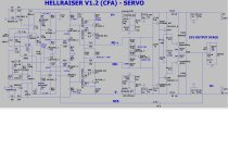
5- Hellraiser V1.2. This used to be the Kypton from "Slewmaster" days. It is a CFA (current feedback) based input stage with a non- inverting servo.
It is the same as the Spookyamp except for the small signal stages. 3PPM is typical @ 10-20Khz.
6 - Infidel V1. This is like the wolverine , but uses LED's for the VAS cascode and CCS. Another LED shows the LTP CCS status. 2-pole miller comp. ,
and a simple layout is presented. Perfect for a first time SMD adventure.
- POWER SUPPLIES - Other protection accessories ...
1 - Arcwelder power board. All through-hole (TH) except for the opto-isolator (OPTO). 20Kuf+ per rail , uses a 17A standard flat bridge
rectifier. On-board MOSFET's are controlled by a external trigger. Fuses and jumpers (for the MOSFET's) are standard.
2 - Arcwelder soft-start - Another "business end" board. ALL AC , dangerous inrush , relays , MOV , and "AC sense" Just a 6 pin connector
with 3 control signals and (+12/+5/ground) to connect to the MCU (control board).
3 - Arcwelder SS relay - standard DC detect , MOSFET relay and rail reference , small form factor. (The other "business end" PCB).
4 - Arcwelder main control board - Arduino NANO standard (pluggable for loading code) Integrated +/- 12V and 5V supplies.
ALL digital with no AC or rail level potentials onboard.
This is a modular audio amplifier "ecosystem". Shortly in the future there will be -
A . protection , bluetooth , and various other accessories. (power meters, etc.)
B. At least 2 more input stages ... since it's modular !
Simple to build , NO special components , and tested to withstand fault conditions ....
Such as saturation , clipping and thermal. Low THD is not the "holy grail" , DIY projects should outperform OEM garbage.
NO China "TOP-CAP" , all Nichicon ,Wima ,ON semi - quality sourcing from trusted distributors.
Layout was tested by the Wolverine team ??? he he .... actually quite excellent !! Slewmaster was the breeding ground for most of
these designs , some of these are still performing after a decade.
Always - MORE to come !
OS
Some of us use 2.1 systems with a sub , we don't need 300W/ch. It seems there aren't many small amps that have
super low distortion , either "big and dirty" or small and dirtier ?
- AMPLIFIERS - IPS/OPS
1 - Arcwelder - mini EF3 ... either a 60W or 100W output stage , just a mini "Wolverine" through-hole PCB. Tested classic Harmon - kardon output
stage with "ripple eaters" . The main VBE is "out on wires" for output device placement. (OPTO) is optional to integrate current sense protection.
2 - Arcwelder - "Beast" EF3 .... 5 pair output transistors. For big "hungry" speakers. Can do 350+ watts ! It also has integrated current sense (OPTO).
3 - Symasui V1.1 ... Hitachi type 2-stage differential (VAS). Everything is cascoded. This IPS should exceed even a Wolverine (blameless) type IPS.
Has more open loop gain at 20Khz (66db) and tremendous gain at low frequencies (120db). Simulates sub PPM (<1)consistently.
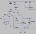
4- Spookyamp V2.1 ... SMD high voltage , low current input stage. Hawksford cascoded self-clamping "Leach amp". ...quite "bombproof".
It has a inverting servo that controls the current sources instead of through standard NFB. 3.8mA VAS is ideal for the "mini EF3". 5PPM is typical.
5- Hellraiser V1.2. This used to be the Kypton from "Slewmaster" days. It is a CFA (current feedback) based input stage with a non- inverting servo.
It is the same as the Spookyamp except for the small signal stages. 3PPM is typical @ 10-20Khz.
6 - Infidel V1. This is like the wolverine , but uses LED's for the VAS cascode and CCS. Another LED shows the LTP CCS status. 2-pole miller comp. ,
and a simple layout is presented. Perfect for a first time SMD adventure.
- POWER SUPPLIES - Other protection accessories ...
1 - Arcwelder power board. All through-hole (TH) except for the opto-isolator (OPTO). 20Kuf+ per rail , uses a 17A standard flat bridge
rectifier. On-board MOSFET's are controlled by a external trigger. Fuses and jumpers (for the MOSFET's) are standard.
2 - Arcwelder soft-start - Another "business end" board. ALL AC , dangerous inrush , relays , MOV , and "AC sense" Just a 6 pin connector
with 3 control signals and (+12/+5/ground) to connect to the MCU (control board).
3 - Arcwelder SS relay - standard DC detect , MOSFET relay and rail reference , small form factor. (The other "business end" PCB).
4 - Arcwelder main control board - Arduino NANO standard (pluggable for loading code) Integrated +/- 12V and 5V supplies.
ALL digital with no AC or rail level potentials onboard.
This is a modular audio amplifier "ecosystem". Shortly in the future there will be -
A . protection , bluetooth , and various other accessories. (power meters, etc.)
B. At least 2 more input stages ... since it's modular !
Simple to build , NO special components , and tested to withstand fault conditions ....
Such as saturation , clipping and thermal. Low THD is not the "holy grail" , DIY projects should outperform OEM garbage.
NO China "TOP-CAP" , all Nichicon ,Wima ,ON semi - quality sourcing from trusted distributors.
Layout was tested by the Wolverine team ??? he he .... actually quite excellent !! Slewmaster was the breeding ground for most of
these designs , some of these are still performing after a decade.
Always - MORE to come !
OS
Attachments
-
LT_ all IPS.zip36.9 KB · Views: 687
-
SMD - PARTS.zip7.5 MB · Views: 584
-
Infidel_V1.0-package.zip913 KB · Views: 589
-
Spookyamp_V2.1_SMD_package.zip1.2 MB · Views: 754
-
Hellraiser_V1.2_package.zip1.1 MB · Views: 594
-
Arcwelder_power_board_package.zip1.6 MB · Views: 564
-
Arcwelder-Beast-EF3_package.zip2.7 MB · Views: 569
-
Arcwelder-mini_EF3_package.zip1.3 MB · Views: 446
Last edited:

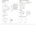
Yup ! I found the VAS/predriver semi's (in SMD) 2SA1419/2SC3649. https://www.mouser.com/datasheet/2/308/1/EN2007_D-2311156.pdf
160V/ 1.5A/ 120Mhz / 10pF Cob. 0.50$ each in SOT-89. Just 3 sq. CM for the heatsink. 15K in stock. NO sourcing issues with SMD.
LTP and other BCxxx BJT's are easier. Duals are available for everything ... even matched precision pairs. A much shorter build guide.
To streamline I will use these on the OPS , as well. But most of the OPS will be big through-hole with a 14pin SIP at the edge.
Even as these designs cancel rail ripple natively , I'll still include the "ripple eaters" on the OPS. 2SA1419/2SC3649 can be used
for these (1.5A) , as well. So 4 SOT-89 , 2 - TO-220 (drivers) , 2 TO-126 (Vbe's) and the 2 big TO3-P/TO-247 (outputs).
I don't have any artwork for SMD. I'll make a deluxe collection for all the LED's/resistors and semi's. I'll use the datasheets reference.
Sound like good nerdy fun !! 😎
Wow , small ... just 1/2 a CM for all this goodness.
Attachments
Cool! more SMT options! I'm curious how the Hellraiser sounds? Might be an interesting project to plug into one of Valery's non switching output stages to see how it measures.
Zetex FZT696/FZT795 have been working good for VAS too. https://www.mouser.ca/datasheet/2/115/DIOD_S_A0001070313_1-2542008.pdf
Zetex FZT696/FZT795 have been working good for VAS too. https://www.mouser.ca/datasheet/2/115/DIOD_S_A0001070313_1-2542008.pdf
You may find fitting spooky on a 50mm x 50mm pcb challenging. I started a smd spooky sometime ago (the original version), got most of the pcb layout done then Sanken EOL the driver and op transistors so I then changed the output stage to ECX10N20/P20 lateral mosfets (SpookyFet). The input stage fits in an area 75mm x 62mm, I moved all the DC voltage regulation off board to the main power supply board. VAS transistors are 2sa1552/2sc4027, Accuphase use these in their amplifiers. Source resistors are vishay WSR 0.15R 5watts.
As a suggestion stick everything on a single pcb, it will make laying out the pcb much easier, I'm not a fan of these daughter board arrangements there's no benefit and the pcb area is the same anyway and you now have to purchase two pcbs.
SpookyFet shares its topology from a series of Sherwood lateral mosfet amplifiers S-6040CP, AM-7040 and AM-8500.
Attachments
Indiglo , did you build it ??
My new spook has fewer parts and runs at a lower VAS Ic. less CM for the SOT's
Hellraiser just has less parts.
I will be using a lot of duals (SOT-223-6's). Just 1 trimmer IPS , 1 for OPS bias.
Thanks for the Zetex option , JW....
My new spook has fewer parts and runs at a lower VAS Ic. less CM for the SOT's
Hellraiser just has less parts.
I will be using a lot of duals (SOT-223-6's). Just 1 trimmer IPS , 1 for OPS bias.
Thanks for the Zetex option , JW....
BTW , I might go single board.
I want to get to the ASKA/Holton audio level of design (board-wise).
I want to get to the ASKA/Holton audio level of design (board-wise).
Spooky 2.1 SERVO... had to invert it. opposite of the hellraiser diamond.
Real nice (below). Servo failure = <.5V offset , Bomb proof !
Both amps are servo failure proof and no servo interaction with the FB path - have not seen this advanced trick in any of the Sherwood's.
in fact , the Sherwood's design is CHEAP. FET CSS to set the cascodes ?? Noisy hot Zeners all over ?? I could eliminate my cold zeners with 79L12/78L12 -
-72db ripple rejection IC regulators. Eliminate 6 parts (and 2 zeners).
YES ! Both Digikey and Mouser have 5-10K of each regulator in stock (SOT-89).
Both circuits are final , I can't believe how hard they are to error. And without the regulators (zener/BJT) 100db+ PSRR !
Indiglo ?? Is that DIPTRACE ? Very nice layout. But I want to go manual with sprint so I can familiarize myself with the SMD world.
Customize my pads (curved pads) and really go anal on the layout. Any tips on how to make pads more friendly for either hand or bake
methods. I don't have much SMD experience ??
OS
Attachments
Last edited:
Looking forward to your developments here Pete!
I enjoy SMD soldering 👍.
I enjoy SMD soldering 👍.
Not yet, I still need to route the op stage and decide on connectors and finish the power supply with its overcurrent protection and dc regulators.Indiglo , did you build it ??
My spooky runs vas at 4.5mA, ltspice tells me vas transistor sits around 230mW, I added copper pours for heatsinking.My new spook has fewer parts and runs at a lower VAS Ic. less CM for the SOT's
I did consider this, but I thought about obsolescence, it happens to smd as well, toshiba eol their low noise smd 2sa1312/2sc3324 transistors. This is why I switched to lateral mosfets from the sanken BJT's that went EOL.I will be using a lot of duals (SOT-223-6's)
Its a good idea, if people want to toaster oven or pan fry their boards they can order a solder paste stencil with the pcb.I might go single board.
I'm using Kicad 7, it has a massive community behind it, I worry about the smaller commercial pcb cad vendors, Kicad will eventually kill them off. My layout was completely manual, I re-laid out the pcb 3 times to get the physical layout looking symmetrical, I found a spooky through hole layout in the old thread that provided ideas to get it where it is now. I spent some time optimising the layout to ensure I didn't have any splits in the bottom ground plane.Is that DIPTRACE ? Very nice layout. But I want to go manual with sprint so I can familiarize myself with the SMD world.
Customize my pads (curved pads) and really go anal on the layout. Any tips on how to make pads more friendly for either hand or bake
methods. I don't have much SMD experience ??
I'm not familiar with Diptrace, I used the standard smd pads for each component. I started out with handsolder pads then changed to the standard size after a Kicad update from V6 to V7. The Kicad handsolder resistor pads are only 0.175mm larger than the standard pads.
If people use fine soldering iron tips and solder diameter 0.381mm or less then standard pad sizes will work for handsoldering, toaster oven and pan fried style. It's not possible to cater for everyone otherwise you'll end up with half a dozen board layouts to maintain.
For example take the wolverine input capacitor, it has every conceivable option for every size capacitor taking up about 15% of the pcb area. My view is stick to standard pad sizes it can only make your life easier.
Since you need to cater for the three soldering methods use thermal reliefs for components connecting to a ground plane to prevent tombstoning when using the toaster oven and pan fried pcb solder reflow methods.
Hi OS, that's too bad 🙁🙁🙁!BTW , I might go single board.
I want to get to the ASKA/Holton audio level of design (board-wise).
I was looking for a simple IPS (Front End only) board for some OPS that I have around. Do not need a lot of gain, or 0.....1% distorsion, but a lot f VAS current is useful (i do not mind if I have to make some simple mod like a Darlington VAS). I have one of my own design but it is a little bulky and not that good, let's say... so not worthy to design a PCB probably. I would go for something like an LME49810, but
 sigh, that is no more available.
Also I like small and and SMD.
Is there something in the various iterations of your designs where there are boards available? Sorry, but in these fifteen years here your design production is soo great that my head is spinning searching in the threads...😁
I am at the final stage...
SMD is a learning curve. I had a discussion about whether my servo's were in the audio path. No , they are not. Unless you consider audio induced rail ripple
as audio .... then everything in a design is "in the audio path".
I had to describe my servo as a "voltage controlled current source" , they still said it was a non-linear way to achieve the end result (uV offset / no 10hz added THD). Oh well.
NO problem fitting spooky on a 50 X 50 mm board. Hellraiser will have its 1-2w feedback resistors on the bottom side. I DO have the bottom side on any
SMD design , great for star grounding and "dirty/noisy" parts.
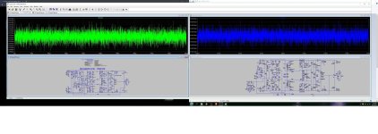
I'll edit my first post for the updated LT simulations. For SMD , I dropped my VAS Ic to 3.7mA. NO added distortion. LATFET or EF3 is nice for such cool low
current IPS's.
NO adjustments , red led of 1.7V is simulated , A newer modern 1.85V red led would just require increasing the current source Re. VAS cascode's LED Vf doesn't matter. NO trimmers , NO big caps in the IPS.
OS
SMD is a learning curve. I had a discussion about whether my servo's were in the audio path. No , they are not. Unless you consider audio induced rail ripple
as audio .... then everything in a design is "in the audio path".
I had to describe my servo as a "voltage controlled current source" , they still said it was a non-linear way to achieve the end result (uV offset / no 10hz added THD). Oh well.
NO problem fitting spooky on a 50 X 50 mm board. Hellraiser will have its 1-2w feedback resistors on the bottom side. I DO have the bottom side on any
SMD design , great for star grounding and "dirty/noisy" parts.
I'll edit my first post for the updated LT simulations. For SMD , I dropped my VAS Ic to 3.7mA. NO added distortion. LATFET or EF3 is nice for such cool low
current IPS's.
NO adjustments , red led of 1.7V is simulated , A newer modern 1.85V red led would just require increasing the current source Re. VAS cascode's LED Vf doesn't matter. NO trimmers , NO big caps in the IPS.
OS
Attachments
Last edited:
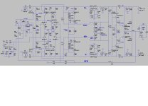
I see you are using the IRFPxxxx's ?? What drivers did you use ? I want my "mini" output board to be EF3 or FET.
Oh , you are using the LED + Vbe !! Like the slewmaster. One builder modified a slewmaster board.
What is U2 ??
OS
Oh , you are using the LED + Vbe !! Like the slewmaster. One builder modified a slewmaster board.
What is U2 ??
OS
I am using IRFPxxx from 2013. (look this thread https://www.diyaudio.com/community/threads/200w-mosfet-cfa-amp.243481/) with Vbe multiplier + red LED and 2SA1381, 2SA3503 as the drivers, and, by the way, not from the slewmaster. U2 is THAT 340.
Damir
Damir
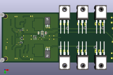
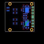
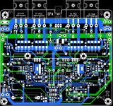
I am progressing. I finally decided on a 4 output baby amp board - 75 X 135mm. Since it's such a small board , I'll recycle the layout to make
a vertical FET version of it.
Same basic WINNING layout as the big Wolverine , it should be a low PPM precision amp. Lots of options , if you are poor 😉 .
- Just populate Q109/Q110 if you want a real small cheap amp (60W). Perfect for satellite speakers. Populate all 4 for a 100W amp.
-This layout is small enough to attach to any sub plate amp or E-waste amp chassis.
-You can mount the tiny SMD IPS's at a right angle or flat. A wolverine IPS would also work with it.
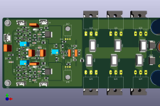
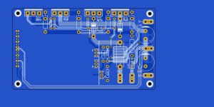
I'm also going to make a supply capacitor PCB - 75 X 150mm , with outputs for 2 amps (stereo) and a series regulator + 7812/7912 regulated
aux output. I might use heatsinked TO-220 diodes , snubbers and all the other extra's.
Since this is smaller amp , all caps will be 4700 - 6800uF X4 63V Nichicon's. 30-0-30 ... 40-0-40V transformers are recommended.
Price , with SMD , the IPS's won't cost more that 15$. I'm also using SMD silver mica's (2.65$ apiece).
Output board has a few SMD's , those .1uF decoupling caps are soooo cheap. Easy to just solder them right at the electrolytic leads.
Why buy 1$+ wima .1uF's ?? All the large resistors will be through- hole.
OS
a vertical FET version of it.
Same basic WINNING layout as the big Wolverine , it should be a low PPM precision amp. Lots of options , if you are poor 😉 .
- Just populate Q109/Q110 if you want a real small cheap amp (60W). Perfect for satellite speakers. Populate all 4 for a 100W amp.
-This layout is small enough to attach to any sub plate amp or E-waste amp chassis.
-You can mount the tiny SMD IPS's at a right angle or flat. A wolverine IPS would also work with it.
I'm also going to make a supply capacitor PCB - 75 X 150mm , with outputs for 2 amps (stereo) and a series regulator + 7812/7912 regulated
aux output. I might use heatsinked TO-220 diodes , snubbers and all the other extra's.
Since this is smaller amp , all caps will be 4700 - 6800uF X4 63V Nichicon's. 30-0-30 ... 40-0-40V transformers are recommended.
Price , with SMD , the IPS's won't cost more that 15$. I'm also using SMD silver mica's (2.65$ apiece).
Output board has a few SMD's , those .1uF decoupling caps are soooo cheap. Easy to just solder them right at the electrolytic leads.
Why buy 1$+ wima .1uF's ?? All the large resistors will be through- hole.
OS
Attachments
Looking forward to those IPS boards.
The Wolverine used a high quality ceramic SMD cap (Vishay VJ HIFREQ Series) for the 1pF in the feedback circuit. Any idea if those are good for an even cheaper alternative for the mica caps ?
The Wolverine used a high quality ceramic SMD cap (Vishay VJ HIFREQ Series) for the 1pF in the feedback circuit. Any idea if those are good for an even cheaper alternative for the mica caps ?
- Home
- Amplifiers
- Solid State
- Spooky and Hellraiser SMD 60W amps (Wolverine compatible IPS)