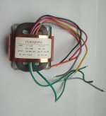
I have this R-core transformer, which has two 110v inputs but has not separate outputs, which I would like to have.
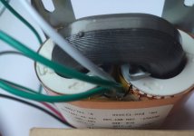
From what I see from the outside it might be very difficult to reach the output wires and re-assemble it properly. Am I right?
Has anyone did anything like that and guide me through it?
From what I see from the outside it might be very difficult to reach the output wires and re-assemble it properly. Am I right?
Has anyone did anything like that and guide me through it?
Attachments
It's hard to get more simple than an R core in terms of how it goes together. It seems like you can do whatever you want including rewind without much difficulty.I have this R-core transformer, which has two 110v inputs but has not separate outputs, which I would like to have.
From what I see from the outside it might be very difficult to reach the output wires and re-assemble it properly. Am I right?
Has anyone did anything like that and guide me through it?
To build the power supply for a phono preamp. The idea was to have separate dual outputs, so I could use two LM317 regulators instead of one 317 (positive) and one 337 (negative).What is the objective of project?
What about the problems there might be when assembling the transformer back together, with external metal wrapping mine has?It's hard to get more simple than an R core in terms of how it goes together. It seems like you can do whatever you want including rewind without much difficulty.
So, the R-core transformer has one center-tapped secondary? In the case the easiest thing may be to get a different transformer. Otherwise, the center tap junction might be buried deep enough that the secondary would have to be unwound and then rewound with two separate windings. If lucky, the center tap junction might be more or less on the surface, but the metal band around the transformer might have to be removed to get access. The band is probably for shielding purposes, and to provide mechanical protection of the windings.
Last edited:
To get a maximum sound experience with your phono amp, connect it to the voltage of your power amplifier. Do the same with your preamp. And with the other sources.
"Primary and secondary windings are designed to be connected in series or parallel. Windings are not intended to be used independently. "
I came across that note from a Triad spec sheet, maybe your R core is not separated for a similar reason?
Dealing with the shield you would likely need to cut it down the center using metal snips/shears. If you don't have those tools then probably not worth attempting. Reassembly; easiest would be to tape the seam with a metal tape. More thoroughly; make a lap patch that overlaps the seam and tape or bond with electrical potting.
What is the pin that the two black-sleeve wires connected to? Does it go to the white wire, with zero Ohms?it might be very difficult to reach the output wires
Then get a very small sharp soldering iron, de-solder those, shorten the black sleeves, and solder short insulated jumpers to the black sleeved wires. Find some way you won't pull them out; maybe feed them back to the gap between windings.
True but. They mean not hundreds of volts apart, such as tube rectifier filament windings. Here, when fully wired, there are only dozens of volts between any two points on the two secondaries.Windings are not intended to be used independently.

just to double-check here (used search function)
"N" in this case just refers to the screen right? I should be grounding this to earth along with the earth connection on the IEC inlet?
"N" in this case just refers to the screen right? I should be grounding this to earth along with the earth connection on the IEC inlet?
I'd discard the idea of using two LM317's instead of fiddling around on that transformer. Feed it from a bridge and two filter 'lytics.
Presumably each bobbin houses a 115 V primary and a 18 V secondary winding. The primaries are isolated, the secondaries are connected in series. What's your objection against the LM327? Is it's performance worse than that of a LM317?
Best regards!
Presumably each bobbin houses a 115 V primary and a 18 V secondary winding. The primaries are isolated, the secondaries are connected in series. What's your objection against the LM327? Is it's performance worse than that of a LM317?
Best regards!
R-core primaries and secondaries are wound on separate bobbins.
https://theaudiocrafts.com/r-core-transformers
Also, one possible reason for using identical regulators for both positive and negative rails could so that characteristics such as, for example, output-z vs frequency, will be the same for both rails. Some people believe SQ can be helped by such means.
Have a look at the pic in #1. All wires protrude from between both bobbins. So I think I was correct with my assumption regarding the winding arrangement.
Best regards!
Best regards!
I don't believe this to be true.R-core primaries and secondaries are wound on separate bobbins.
https://theaudiocrafts.com/r-core-transformers
Years ago, I had a Kitamura-Kiden subcontractor make a few R-core prototypes with the primary and secondary windings confined to separate legs of the core (aka split-bobbin construction), and the result was an unacceptable level of vibration and hum.
What I gathered from the communications that followed is that while R-cores have two distinct bobbins that may lead one to assume that the primaries and secondaries each have their own dedicated bobbin, in reality the load balancing necessary to cancel out vibration and hum is accomplished through interleaving of the windings on both bobbins.
That said, my experience was around 20 years ago, and it is possible that Kitamura-kiden have subsequently advanced their technology so that they are capable of making R-cores with true split-bobbin construction and no vibration and hum.
Okay. I just checked to see and it appears you guys are right. Unmeasurable capacitive coupling between the two primary windings. Yet measurable capacitance between primaries and secondaries. At least the R-cores I have from China appear to be made that way. Back to other split bobbin designs then, or else R-cores that actually have the isolation properties claimed for them.
- Home
- Amplifiers
- Power Supplies
- Splitting the outputs on an R-core transformer.