Hi Everyone,
I have a step-down toriod transformer. Really nice quality, USA made.
Its 240v to 110V, 1000W
So long as the load is equal on both rails this should work to split the rails?
the load an amp puts on the rails should be symmetric right?
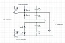
please ignore part values, its just for an example.
It just seems like I'm missing something.....
I have a step-down toriod transformer. Really nice quality, USA made.
Its 240v to 110V, 1000W
So long as the load is equal on both rails this should work to split the rails?
the load an amp puts on the rails should be symmetric right?
please ignore part values, its just for an example.
It just seems like I'm missing something.....
Attachments
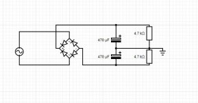
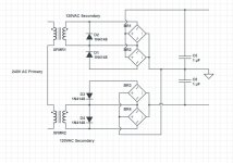
Here is a half wave circuit.
If no good then you really need a CT transformer for good performance.

If no good then you really need a CT transformer for good performance.
For approximately symmetrical loads, you can use a two-transistor splitter, in the Quad style.
Another option is to make the amplifier itself work as a rail splitter, but it requires some modification
Another option is to make the amplifier itself work as a rail splitter, but it requires some modification
the load an amp puts on the rails should be symmetric right?
It is symmetric on average over time, but there are constantly different load pulses from different sides. It will not work as suggested.
Jan
Problem is load will never ever be exactly the same on both rails, difference will be integrated by caps and swing "center" point towards one side or anotherSo long as the load is equal on both rails this should work to split the rails?
the load an amp puts on the rails should be symmetric right?
It just seems like I'm missing something.....
Rsistors will balance small errors, but only to the tune of their own idle current.
Servos do exactly the same, only they can provide higher balancing current on demand, but are not a magic solution.
FWIW: I wind my own transformers so adding a center tap is easy, and if ordering one of course choose what´s needed, but now and then, being a pack rat, end with one or more "orphans" pulled from some junked amp.
To use them someway, I designed and made a few copies of a "universal amp" PCB, it can use:
* single supply (has capacitor coupled output) anywhere between 12V and 100V +V
* any power transistor (according to supply voltage and load) from TIP31/32 to MJ150** and anything in between, any casing: TO3 metallic, TO220/218/247 ; complementary or quasi, Darlingtons, even power MosFets, etc.
A very basic no frills circuit, convertible from one to other type placing a few jumpers, only problem is that it "justifies" hoarding, since now "anything" can be assembled on it, coupled to a simple cabinet, and sold or traded.
Main advantage: it empties junkbins from "mystery" transformers (such as yours) and power transistors.
This cold rainy weekend I turned a single winding (no centertap) 32VAC transformer, a couple TIP41 plus remaining components, into a 30ish Watt amp driving an 8" 4 0hm speaker and a Piezo (everything pulled from the junk room) , mounted in a junk empty cabinet , sawed off to size.
Surprisingly loud, I am using it to listen to SF audiobooks while I wind "real" transformers for commercial products. 😱
So if you want to use your transformer, suggest you do something similar.
EDIT: TELL US what specs (Voltage/Current/VA) does your transformer have and what do you intend to power with it.
I did it for my 1st OTL amp 35 years ago ... still working and keep Altec voice coils alive too 😀 A clever idea to avoid offset of output rail 😉So long as the load is equal on both rails this should work to split the rails?
the load an amp puts on the rails should be symmetric right?
It's not worth trying as the midpoint would simply walk away from its mean position in due course. You could actively split the rails but then, that would be another power converter, which if operated closed-loop, would definitely give better performance. Two MOSFETs, gate driver few diodes, transistors, caps, opamps/comparators required.

Last edited:
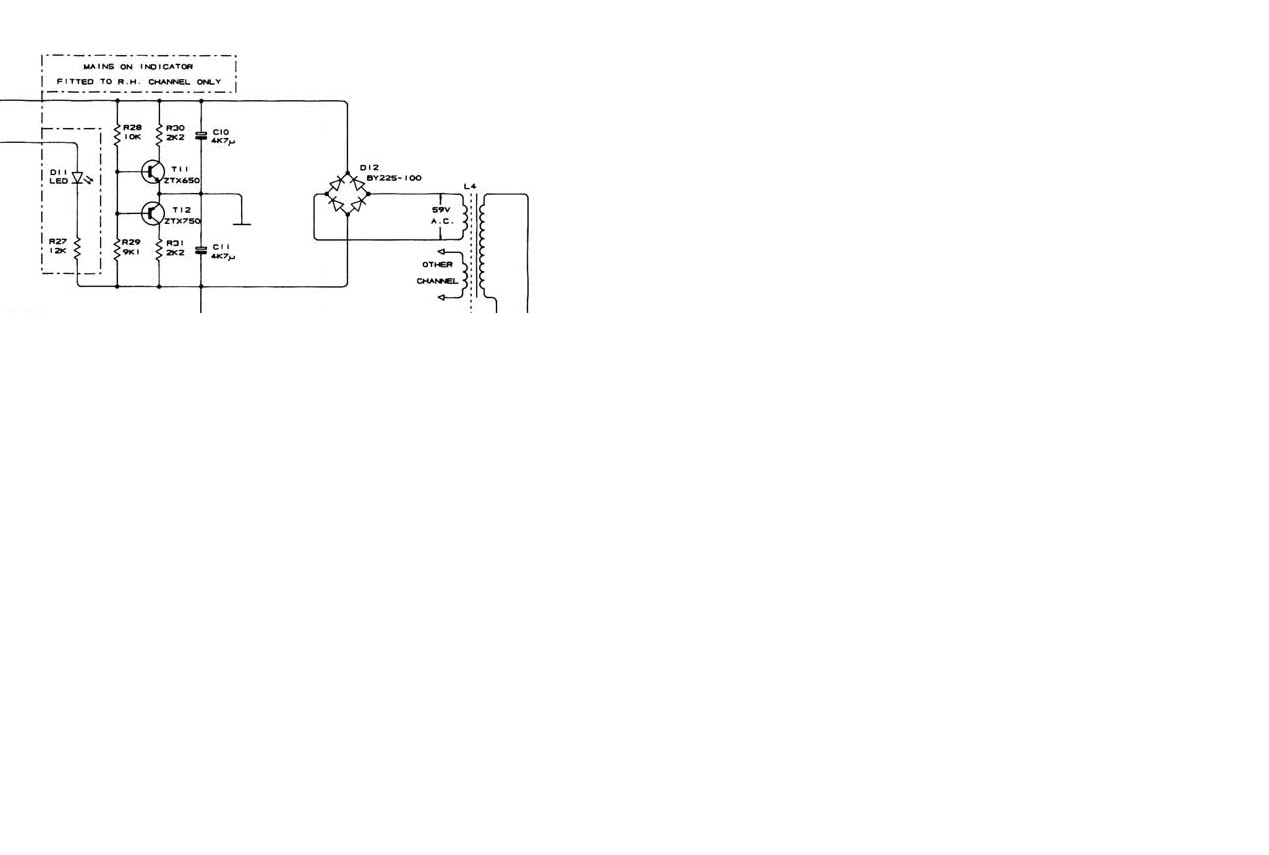
The active rail splitter I mentionned actually works, it has been used for years in the Quad 606 among others:

I have also developed a smarter solution: a lossless, reactive rail splitter:
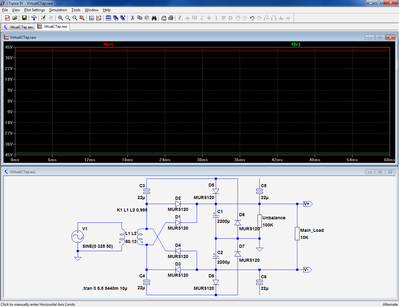
C3, 4 and D5 --> D8 create the equivalent of a resistive bridge, but because it uses reactances rather than resistances, it dissipates no power.
The virtual ground thus synthesized is not infinitely stiff: it has an internal resistance determined by the size of C3, 4.
In the sim, the circuit is shown with a 10K load, and a 100K imbalance (10%).
The symetry between the +/-44V rail remains good.
To make the tap stiffer, the capacitors can be increased
I have also developed a smarter solution: a lossless, reactive rail splitter:
C3, 4 and D5 --> D8 create the equivalent of a resistive bridge, but because it uses reactances rather than resistances, it dissipates no power.
The virtual ground thus synthesized is not infinitely stiff: it has an internal resistance determined by the size of C3, 4.
In the sim, the circuit is shown with a 10K load, and a 100K imbalance (10%).
The symetry between the +/-44V rail remains good.
To make the tap stiffer, the capacitors can be increased
Attachments

I'm thinking a 2500W amp board from Sure.
WONDOM | STORE
120V * 1.41 = 169v ish
This amp is rated 2500w into 6ohm %10 distortion.
My guess is more like 1000W `un distorted'
I was interested in using the transformer it for a +/- but I doubt the 1/2 wave rectification will be good.
Has anyone had experience with these amplifier modules?
WONDOM | STORE
120V * 1.41 = 169v ish
This amp is rated 2500w into 6ohm %10 distortion.
My guess is more like 1000W `un distorted'
I was interested in using the transformer it for a +/- but I doubt the 1/2 wave rectification will be good.
Has anyone had experience with these amplifier modules?
The active rail splitter I mentionned actually works, it has been used for years in the Quad 606 among others:
I have also developed a smarter solution: a lossless, reactive rail splitter:
C3, 4 and D5 --> D8 create the equivalent of a resistive bridge, but because it uses reactances rather than resistances, it dissipates no power.
The virtual ground thus synthesized is not infinitely stiff: it has an internal resistance determined by the size of C3, 4.
In the sim, the circuit is shown with a 10K load, and a 100K imbalance (10%).
The symetry between the +/-44V rail remains good.
To make the tap stiffer, the capacitors can be increased
Where do C5 and C6 connect to?
You do not need a split rail for this module: just use the 110V AC rectified and filtered the normal way, and that's it.
You need a big rectifier bridge, a big cap, and some kind of soft-start to avoid tripping the circuit-breaker
You need a big rectifier bridge, a big cap, and some kind of soft-start to avoid tripping the circuit-breaker
I used a similar circuit in a transistor tester to get + and - 12 volts, and zero volts from 24 volts DC. I just used a couple of transistors to split the rail.
That's all you need: it is a BTL output, and a single supply is sufficient.I have ~50 x 820uf 200v capacitors and a 50A bridge rectifier.
Some kind of soft-start will probably be needed for such a big supply

- Home
- Amplifiers
- Power Supplies
- Split rail from transformer with no center tap