Hi everyone!
Today I am tired and my mind feels dull and quite worthless.
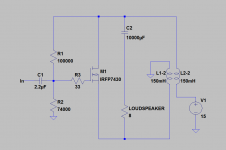
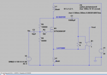
I have been thinking about a "Concertina" split load phase splitter based amp with a bifilar winded choke as load.
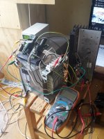
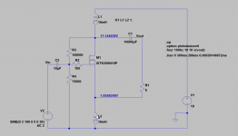
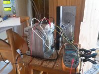
I ended up with the circuit above, and it works nice. I am playing Melody Gardot March for Mingus as I type this.
I can't say that I am impressed by the sound in any way though.... There is nothing wrong really, its just a bit dull and boring to listen to.
The same IRFP7430 in a Zen type amp sounds marvellous with abundant muscle and joyful vividness.
Is the transformer-core magnetized in the above schematic? I can't grasp this circuit today. What could be the reason it sounds so dull?
I tried to couple the two windings differently and the music just disappeared, so I guess that was the wrong way.
Thankful for any comments on this, since my brain is on sick-leave today, an just flat out refuses to do anything meaningful...
Cheers,
Johannes
I connected this amp to my computer soundcard and the sound quality increased substantially. It seems more sensitive to the signal source then other amps I have built and tested. It has no voltagegain. It is a powerbuffer, so I don't get a lot of power from it. I need a good preamp.
I have been listening to Biosphere, Yazzo, Frankie goes to hollywood and some Miles Davis, and it kind of grows on me. It might not have the same immediate presence and vividness that the same IRFP7430 has in a normal Zen amp, but it is very well behaved. Clean, fast and with a nice dynamic punchy bass reproduction.
Cheers,
Johannes
https://youtu.be/ewTKcSiXlH8
Here is a video showing me varying the current through the amp while playing music.
There is a lot of audible distortion with less then 50 mA of current through the amp.
With 50 mA it is quite nice sounding. With 500 mA it sounds somewhat warmer and fuller with a smoother treble, but the difference is not that large compared to 50 mA.
This is really strange. I don't understand how it can play nice, clean and smooth music with only 50 mA?
I simulated something quite similar but with 900 mA current instead.
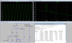
I don't know how to simulate a bifilar choke, so I used two separate 0.55 ohm 150 mH chokes.
Cheers,
Johannes
Here is a video showing me varying the current through the amp while playing music.
There is a lot of audible distortion with less then 50 mA of current through the amp.
With 50 mA it is quite nice sounding. With 500 mA it sounds somewhat warmer and fuller with a smoother treble, but the difference is not that large compared to 50 mA.
This is really strange. I don't understand how it can play nice, clean and smooth music with only 50 mA?
I simulated something quite similar but with 900 mA current instead.

I don't know how to simulate a bifilar choke, so I used two separate 0.55 ohm 150 mH chokes.
Cheers,
Johannes
You could try to change the choke into a transformer by winding a secondary (if room on the bobbin allows).
A 4:1 step down ratio would present the fet with a much better load and this way I would not be surprised if you'd get really good sound quality.
You don't need the coupling cap then because of the galvanic isolation.
However your source will have to provide more signal to compensate the loss in gain.
Thanks Pieter for some suggested changes and a possible route of development.
It would be nice with a transformercoupled output without the DC blocking cap, but I don't like the thought of rewinding the transformer.... It is not fun hand-winding them...
I had this bifilar choke left over from a previous project, and I just wanted to test this idea I have been mulling over for some time now. The split load phase splitter can be seen as a choke loaded Zen amp with lots of degeneration and a low output impedance or as the phase splitting stage in Nelson Pass PLH amp but beefed up to directly drive the speaker.
The idea being that it is inherently very linear and fast without any extra circuitry and feedback. It has 2 X voltage gain. The large bifilar choke does not have to handle large DC currents that saturate the core. The chokes adds two "virtual" rails which enables much larger voltage swings.
With a 15 volt powersupply and 1.5 amps through the amp I can get 9.5 watts into 8 ohms.
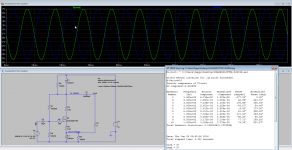
Not bad performance considering the low voltage from the powersupply and the extreme simplicity of only using one single active device.
Cheers,
Johannes
It would be nice with a transformercoupled output without the DC blocking cap, but I don't like the thought of rewinding the transformer.... It is not fun hand-winding them...
I had this bifilar choke left over from a previous project, and I just wanted to test this idea I have been mulling over for some time now. The split load phase splitter can be seen as a choke loaded Zen amp with lots of degeneration and a low output impedance or as the phase splitting stage in Nelson Pass PLH amp but beefed up to directly drive the speaker.
The idea being that it is inherently very linear and fast without any extra circuitry and feedback. It has 2 X voltage gain. The large bifilar choke does not have to handle large DC currents that saturate the core. The chokes adds two "virtual" rails which enables much larger voltage swings.
With a 15 volt powersupply and 1.5 amps through the amp I can get 9.5 watts into 8 ohms.

Not bad performance considering the low voltage from the powersupply and the extreme simplicity of only using one single active device.
Cheers,
Johannes
I am spoiled by the triode character of my Bastode Schade feedback amp, so any amp not having this very vivid and lively character sounds dull and boring to me... Good triode amps and SIT amps together with high efficiency loudspeakers seems to have this effect.
I built a simple Bastode Schade feedback preamp from an IRF9530 and an IRF3706 I had lying on my table. 100 ohm drainresistance. 1000 ohm + 100 ohm feedback resistor voltage divider for 11 times voltage gain.
All of a sudden all the vivid joyous fun is back again. Music is emotionally engaging and very "alive". It is not a strict and neurotic obsessive focus on avoiding any error with the result of presenting the music as simple test tones devoid of any traces of life.
I am even more surprised by the amount of undistorted power I get from the split load phase splitter amp with only 100 mA quiescent current. The preamp starts clipping before the amp.
This was supposed to be a simple test of some ideas. I want to hear what a fet based split load phase splitter sounds like, and how changes to the circuit changes the character of the amplifier stage. I want to test some deliberate unbalance to get some controlled amount of positive going or negative going second order harmonics like Nelson Pass does in his F6 article. Say 100 to 1000 ohms across one of the windings of my large bifilar choke.
This turned out to be a most worthwhile exploration of a simple single stage amp.
Cheers,
Johannes
Thanks ZM!!!
That seems simple enough. I hope I can get a better simulation soon.
Cheers,
Johannes
That seems simple enough. I hope I can get a better simulation soon.
Cheers,
Johannes
Thank you tordnilsson!
I don't know if this is interesting or just plain nuts...
I am having a blast playing with this though.
Cheers,
Johannes
I don't know if this is interesting or just plain nuts...
I am having a blast playing with this though.
Cheers,
Johannes
...that looks simple alright
😀
It started out quite simple, but quickly went downhill from there.... 😀
Cheers,
Johannes
I am overwhelmed by the overly enthusiastic response I got from this idea.... 😉
Joke, aside. I guess nobody sees the possible benefits of this amp (or maybe it is just not very interesting to anyone except for me and my adventurous experiments with fun and sometimes unusual circuits).
I would call this a buffer, even though it has roughly two times voltage-gain. It seems to have a quite low output impedance, since the bass from my BIB is very tight and punchy, as opposed to the quite full and blooming bass I get from amps with higher output impedance. The output voltage does not change much between the same signal into an 8 ohm load and into a 2 ohm load in simulation. Only a few percent.
Since the amp has a balanced output there will be a lot of cancellation of even order harmonics (distortion). It is very clean and well behaved until it starts to clip. It is also very quiet.
An even bigger advantage with the balanced output that is not easily seen in simulation is that a reactive load coupled to ground plane will create lots of disturbances when the ground plane that is often the voltage reference for most of the circuitry in the amp, suddenly starts moving up and down in voltage due to the real world resistance transforming speaker currents into voltages. Most designers seems to think that the ground-plane is a super-massive black hole and the cables and PCB traces leading to ground is square-miles of superconducting cables perfectly attached to the super-massive black hole.
Since real world cables and PCB-traces has some real world resistance, this usually upsets the function of the amp when called upon to do some honest work.
This is easily heard when comparing an amp bridge-tie loaded to the same amp with the load between the output and the ground plane.
With balanced amps (SoZ, Circlotrons, bridge-tie loaded amps etc) there is often a calmness that is very difficult to describe and even more difficult to quantify.
This split load phase-splitter amplifier does not have the load connected to the ground-plane. There is a quite good isolation and the amp is very forcefully balanced, to cancel distortion and create a undisturbed and calm environment for the outputs to drive the loudspeaker - isolated from the rather noisy environment that is the power-supply and taxed ground-plane.
I hope my rambling rant and crazy ideas makes at least some sense. Now I am off to listen to some music.
Cheers,
Johannes
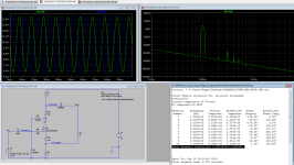
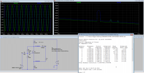
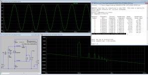
Here is a simulation of a power-resistor loaded split load phase-splitter amplifier driving an 8 ohm load with a 15.4 volt (p-p) signal. Very low distortion for a such simple amp and only resistors as drain and source load.
The FFT clearly shows the cancellation of even order harmonics.
Cheers,
Johannes
As I said in my first post: my brain was on sick-leave and refused to do anything meaningful the day I built this last experimental amplifier.
The core of the large bifilar choke is magnetized by the current. When I traced the wiring again today, I saw that the current flows the same way through both windings. Luckily for me, the core is somewhat air-gapped. This might partly explain why I find the amp somewhat lacklustre in dynamics and vividness.
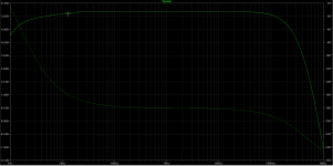
Tomorrow I hope I can test this amp with my aircored 2 x 16 mH bifilar choke. It looks good in simulation at least. Only down one dB at 20 Hz or so. I guess this is because of the balanced operation and the quite large DC resistance of the windings.
Cheers,
Johannes
I believe there are some misleading things in your sim , if I'm understanding rules of .four analysis - it is referenced to gnd , while your speaker is nested between two chokes , so you're ignoring things developing in L2
put e.asy across speaker leads , connect - out to gnd , mark + out as Out, give it value 1
that way you'll translate floating outputs to gnd
put e.asy across speaker leads , connect - out to gnd , mark + out as Out, give it value 1
that way you'll translate floating outputs to gnd
I believe there are some misleading things in your sim
Yes, most certainly... I am a complete noob when it comes to LTSpice, so I try to keep it as simple as possible, and I don't dwell much on any discrepancy between the simulation and the real world results - as long as they are consistent between different simulations.
Your analysis and suggested changes are most valuable to me. Thanks for easy to understand, clear and concise instructions in how I can use transformers and e.asy to better the simulation. This makes it much easier for me, and I really appreciate it! 🙂
I try not to delve to deep into every aspect since I view a simulation as a crude approximation. It is a great tool test ideas and see what has an effect and what does not have an effect on the results. I don't take the numbers as absolute facts. I hope any inaccuracy or discrepancy between the simulation and the real world results are at least reasonably consistent between my different simulations.
I omit all the parallel and series capacitances and inductance leakage between windings in my transformers, because I want to keep it simple and consistent between my different sims.
Since I simulate with a 8 ohm resistor as a load instead of a highly reactive loudspeaker, I guess it is not that important if other parts of the simulation is crude approximations too.
Cheers and thanks!
Johannes
yup , you got it right , about tests in vivo being most important
however , I'm finding proper sim (proper as much I know, which isn't so much ) most important in area showing critical factors , not rosy predictions
so every effort in that direction is beneficial
however , I'm finding proper sim (proper as much I know, which isn't so much
 ) most important in area showing critical factors , not rosy predictions
so every effort in that direction is beneficial
- Home
- Amplifiers
- Pass Labs
- Split load phasesplitter amplifier with bifilar choke load
