Hi All,
Great community here, my first post. Sorry for the long post but I figure a thorough question might get better answers.
I saw an Uncle Doug video on Youtube where he was going through an old Electromuse A-46 guitar amp. >> Let's Explore and Repair a 1946 Electromuse Amp - YouTube
He was able to find a circuit diagram for it at dougcircuits.com (no relation to him), which I also found. >> https://www.dougcircuits.com/electromuseA46.jpg
I was curious about the NFB aspect of this amp, and how it fed back to the common cathode connection between the two phase inverter stages, so I tried to recreate a similar design in LTspice.
I am neither a spice or tube amp expert, this is my fist go at using tubes in a simulation. I was able to find models for the 6SN7 (by Duncan Amps) and 6V6 (by Jeroen Boschma, on Github I think), both uploaded below.
Most pentode models only include four pins, so I started with the generic pentode symbol that comes standard in LTspice and deleted the suppressor grid. The original pin list order (1-5) for the generic symbol is K, G1, G2, G3, A, which I changed to P, S, G, K to match the model.
Q1. how do you know what order the pins are on the symbol - top to bottom, order of creation etc?? By reversing the pins to match the model (as is required), how does the pinout keep the same relationship to the symbol?
I also tried to create an output transformer model using individual inductors and resistors and together with values derived from the Transformer Models Rev. 4 spreadsheet created by Rober McLean (thanks Robert!). I did not try to create a sub-circuit as this would require me to create an symbol for it which I have never done before.
I was going for an 8 Ohm output using the Generic8K transformer entry for PP rather than the 2 Ohm output of the A-46. Please note I have not included the NFB loop as I am yet to get the open loop amp to simulate properly.
I am also a little skeptical of the suspiciously high 600K resistors throughout this circuit, I could not spot any in UD"s video. The simulated circuit only includes the phase inverter and forward at this stage.
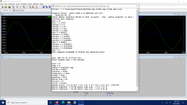
I have attached the .asc file for the circuit below. If I run a simulation I get 771kV (< not a typo) at the grid of U4. If I remove the series resistors from both the primary and secondary side of the OT and add the resistances back as an attribute of the inductors themselves (by right clicking), I get much better results but the simulation time goes from seconds to 10s of minutes.
Q2, when modeling a transformer, does it make a difference if using external resistances or specifying them as an attribute of the inductor itself? Obviously this is changing the behavior of the transient analysis in LTspice but should it matter in the circuit?
I would appreciate any additional pointers on where I may be going wrong.
Great community here, my first post. Sorry for the long post but I figure a thorough question might get better answers.
I saw an Uncle Doug video on Youtube where he was going through an old Electromuse A-46 guitar amp. >> Let's Explore and Repair a 1946 Electromuse Amp - YouTube
He was able to find a circuit diagram for it at dougcircuits.com (no relation to him), which I also found. >> https://www.dougcircuits.com/electromuseA46.jpg
I was curious about the NFB aspect of this amp, and how it fed back to the common cathode connection between the two phase inverter stages, so I tried to recreate a similar design in LTspice.
I am neither a spice or tube amp expert, this is my fist go at using tubes in a simulation. I was able to find models for the 6SN7 (by Duncan Amps) and 6V6 (by Jeroen Boschma, on Github I think), both uploaded below.
Most pentode models only include four pins, so I started with the generic pentode symbol that comes standard in LTspice and deleted the suppressor grid. The original pin list order (1-5) for the generic symbol is K, G1, G2, G3, A, which I changed to P, S, G, K to match the model.
Q1. how do you know what order the pins are on the symbol - top to bottom, order of creation etc?? By reversing the pins to match the model (as is required), how does the pinout keep the same relationship to the symbol?
I also tried to create an output transformer model using individual inductors and resistors and together with values derived from the Transformer Models Rev. 4 spreadsheet created by Rober McLean (thanks Robert!). I did not try to create a sub-circuit as this would require me to create an symbol for it which I have never done before.
I was going for an 8 Ohm output using the Generic8K transformer entry for PP rather than the 2 Ohm output of the A-46. Please note I have not included the NFB loop as I am yet to get the open loop amp to simulate properly.
I am also a little skeptical of the suspiciously high 600K resistors throughout this circuit, I could not spot any in UD"s video. The simulated circuit only includes the phase inverter and forward at this stage.
I have attached the .asc file for the circuit below. If I run a simulation I get 771kV (< not a typo) at the grid of U4. If I remove the series resistors from both the primary and secondary side of the OT and add the resistances back as an attribute of the inductors themselves (by right clicking), I get much better results but the simulation time goes from seconds to 10s of minutes.
Q2, when modeling a transformer, does it make a difference if using external resistances or specifying them as an attribute of the inductor itself? Obviously this is changing the behavior of the transient analysis in LTspice but should it matter in the circuit?
I would appreciate any additional pointers on where I may be going wrong.
Attachments
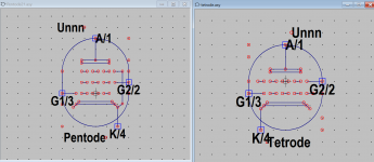
Don't mess with LTSpice's symbols unless you are an expert.
Use the "tetrode" icon from LTSpice's standard MISC component list.
It has just the 4 electrodes which your models require.
This std tetrode requires that the model lists the pins in sequence Plate, Screen, Control Grid, Cathode (P,S,G,C) which is the same as Anode, Grid2, Grid1, Kathode (A,G2,G1,K).
It sometimes happens that other models use a different pin sequence, in which case you should change the subcircuit line in the model file, rather than Spice's symbol file.
The formulas in the model use the pin names listed in the model's subcircuit statement.
That makes the connection.
Also you can either use separate resistors for the DC resistance of inductors or put the DC values as "series resistance" into the list of inductor properties. Don't think it makes much of a difference, unless Spice treats them as distributed DC resistance - which might be the case and if so would be the more realistic case.
Attached a new .asc file in a ZIP, all I changed is that I substituted the tetrodesymbol for the pentode and it seems to work as is otherwise.
The 600kohm are the grid leak resistors which should be in a range 100k to 1000k depending on tube's requirements.
Be aware that LTSpice treats "m" as milli, so if you want to use 1Mohm you have to either enter this as 1000k or 1M (capital M).
Attachments
One small correction: LTspice unit abbreviations are not case sensitive so LTspice is going to treat both 1m and 1M as 1 milliohm. If you mean 1 megohm then you must show it as either 1Meg or 1meg, not 1M, or 1000k as you indicated.
damn right, meg, MEG, Meg it is ... not 1M ... je suis désolé ...
another remark:
the two 600k at the plates of 6SN7 are not grid leaks of course but load to the triodes;
in an amp for audio this could be considered too high because plate voltage is quite low, around 14 volts; for a guitar amp this might be intentional to produce distortion ...
another remark:
the two 600k at the plates of 6SN7 are not grid leaks of course but load to the triodes;
in an amp for audio this could be considered too high because plate voltage is quite low, around 14 volts; for a guitar amp this might be intentional to produce distortion ...
Thanks guys.
To be on the safe side, I created a new 'tetrode' symbol by editing the existing pentode, editing the pin assignments, and then doing a "save as" to save the new symbol. Once created I backed out all the changes and left original pentode symbol as is.
The confusing part is that LTSpice's standard for the pentode is opposite in pin assignment to even it's own triode and tetrode, i.e. the latter two assign the anode as pin one and count up towards the cathode, the pentode assigns the cathode as pin 1 and counts towards the anode.
I didn't reorder the pin sequence in the model because I wasn't sure that if I did, whether it would require any of the following lines to be reordered as well. Apparently not - now I know! Thanks.
I had thought about dropping in the original LTSpice tetrode symbol but other strange behavior confused me, and that behavior continues. Your returned .asc file with the tetrodes swapped in works like a charm... so I went back to my original and made the same change. However mine refuses to run a full transient response, all I can see is the 400 Hz waveform before the first coupling capacitor from the source. Nothing after that shows up, not even DC operating points.
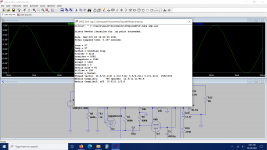
Below are the error logs from both versions.
In reference to the 600k resistors, I was more curious as to the impact of using them as Plate resistors on the 6SN7s (and preceding pre-amp stage in the original A-46 circuit, not included here) than as the grid leak resistors. But as I mentioned above, your version of the circuit works, so I can play with that value to see how it affects the gain/operation.
Keeping my fingers crossed that you may have some insights as to what ails my version.
To be on the safe side, I created a new 'tetrode' symbol by editing the existing pentode, editing the pin assignments, and then doing a "save as" to save the new symbol. Once created I backed out all the changes and left original pentode symbol as is.
The confusing part is that LTSpice's standard for the pentode is opposite in pin assignment to even it's own triode and tetrode, i.e. the latter two assign the anode as pin one and count up towards the cathode, the pentode assigns the cathode as pin 1 and counts towards the anode.
I didn't reorder the pin sequence in the model because I wasn't sure that if I did, whether it would require any of the following lines to be reordered as well. Apparently not - now I know! Thanks.
I had thought about dropping in the original LTSpice tetrode symbol but other strange behavior confused me, and that behavior continues. Your returned .asc file with the tetrodes swapped in works like a charm... so I went back to my original and made the same change. However mine refuses to run a full transient response, all I can see is the 400 Hz waveform before the first coupling capacitor from the source. Nothing after that shows up, not even DC operating points.
Below are the error logs from both versions.
In reference to the 600k resistors, I was more curious as to the impact of using them as Plate resistors on the 6SN7s (and preceding pre-amp stage in the original A-46 circuit, not included here) than as the grid leak resistors. But as I mentioned above, your version of the circuit works, so I can play with that value to see how it affects the gain/operation.
Keeping my fingers crossed that you may have some insights as to what ails my version.
Attachments
Found it!
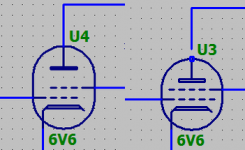
When I earlier replaced the modified pentodes with tetrodes, I deleted both first and then replaced them. Then I guess I replaces the lower one first, followed by the upper. Because LTSpice labels components in order using the first available number, the lower output tube became U3 while the upper became U4.
This was opposite to the returned Tube Amp X circuit. Without deleting them, I simply moved the existing U3 into the upper position, and U4 into the lower. Then everything magically worked.
I have no idea why LTSpice would behave this way but if anyone can explain it, I would love to know.
With the circuit still in the same open loop configuration and fed with 200 mV p-p, it outputs an average 55.75 V p-p at the 6V6 plates and 3.13 V p-p at the secondary of the output transformer. Given the 6V6s drive the OT in anti-phase simultaneously, I assume the primary sees twice the total voltage swing, or 111.5 V p-p. A reduction ratio of 35.62:1.
The inductances alone (44.68 H vs 46.1 mH) suggest a ratio of 31.31:1, so I'm also guessing any difference is due to the series resistance of the windings.
...Most pentode models only include four pins, so I ... deleted the suppressor grid....
Why?
Tie G3 to K and be done with it. SPICE won't know the difference.
Mucking with models is a fine way to lose track of what problem SPICE thinks you have put to it. As I think you found.
If you need to replace Tetrode asy with Pendode asy and still use Tetrode model (Paint tool always output model to suit Tetrode ays), make sure the pin orders in your new Pentode asy is same as original Tetrode asy. If you use Koren model which output to suit another Pentode asy you should check again as it will have different pin order as it might not work with your new Pentode asy. The model pin order should match asy pin order in any case. E.g:
.SUBCKT 6F12P P G2 G K ; LTSpice tetrode.asy pinout 1=P, 2=G2, 3=G, 4=K
* .SUBCKT 6F12P P G K G2 ; Koren Pentode Pspice pinout 1=P, 2=G, 3=K, 4=G2
.SUBCKT 6F12P P G2 G K ; LTSpice tetrode.asy pinout 1=P, 2=G2, 3=G, 4=K
* .SUBCKT 6F12P P G K G2 ; Koren Pentode Pspice pinout 1=P, 2=G, 3=K, 4=G2
Attachments
Last edited:
Using LTSpice's generic pentode symbol, I started with the suppressor grid connected to the cathode, but this did not satisfy the 4-pin model; LTSpice saw too many pins in the symbol and spat out an error. The only way was to match them numerically.
Koonw, your pentode symbol looks good and would probably work fine because the suppressor grid is not extended out to an active pin (i.e. it does not go to a pin with a square box around it) but rather, is simply connected internally to the cathode. This, imo, is more accurate than using a tetrode symbol but will make no difference to how the model sees it or works.
The confusing part is that LTSpice's pentode has its pins labelled 1-5 starting from the cathode.
I am yet to find anything that explains the relationship between the Pin List order (just the numbered sequence) and the boxes in the symbol .asy file. The boxes in the .asy file are not labeled. How do we know, for example, that the top box (which represents the connection to the anode) is pin 1?
Southern Cross;6821849 When I earlier replaced the modified pentodes with tetrodes said:LTSpice does not care how the components are numbered, pretty shure about this.
My best guess is that when you replaced the pentode by the tetrode, you may have overlooked the little gap which leaves the plate disconnected. This happens because the tetrode symbol is a tad shorter than the tetrode.
Maybe you just mechanically, automatically, ah... magically fixed that when you flipped tetrodes ?
Attachments
I am yet to find anything that explains the relationship between the Pin List order (just the numbered sequence) and the boxes in the symbol .asy file. The boxes in the .asy file are not labeled. How do we know, for example, that the top box (which represents the connection to the anode) is pin 1?
open the file whatever.asy with a text editor and look for lines like these:
SYMATTR Description This symbol is for use with a subcircuit macromodel that you supply.
PIN 0 -48 NONE 0
PINATTR PinName Anode
PINATTR SpiceOrder 1
PIN 48 0 NONE 0
PINATTR PinName Screen
PINATTR SpiceOrder 2
... got the idea ... ?
Last edited:
Tetrode model has only 4 pins then you need a 4 pin asy, and if you use a 5 pin asy you can just add another pin to your model.
SUBCKT 6F12P P G2 G K G3; LTSpice tetrode.asy pinout 1=P, 2=G2, 3=G, 4=K 5=G3
The empty pin 5 will be ignored, but it will be included in netlist export to extenal PCB layout software. Likewise you can add pin 4, 5 to triode model and added pin 4,5 in triode asy. You can find model that has G3 modeled, heptode tube model .
Nope. Spotted the little gaps and took care of them. Even zoomed right in to make sure the connections were made.
I suspect that even if there were a gap (which I am sure there wasn't), why would this cause no DC readings and signal to disappear after C3 (the input coupling cap)?
Also, the error log would have shown a missed connection.
It's these seemingly inexplicable things that make LTSpice a crapshoot to use sometimes.
open the file whatever.asy with a text editor and look for lines like these:
SYMATTR Description This symbol is for use with a subcircuit macromodel that you supply.
PIN 0 -48 NONE 0
PINATTR PinName Anode
PINATTR SpiceOrder 1
PIN 48 0 NONE 0
PINATTR PinName Screen
PINATTR SpiceOrder 2
... got the idea ... ?
Didn't know you could do that. I took a look and it seems logical but I don't think it answers my question.
The above lists the spice order and the pin names, which you can get from the Pin/Netlist table once inside the symbol editor. We can rename the pins to get correlation between the numbering (spice order) and the model.
What I don't understand is how LTSpice associates the boxes (pins) with the above.
Say we had a generic symbol drawn (a black box whose operation is only modeled in a subcircuit). The symbol is a square with a pin on each side and no labels. How do you relate the pin numbers?
Thanks Koonw, good to know we have this flexibility.
I am yet to find anything that explains the relationship between the Pin List order (just the numbered sequence) and the boxes in the symbol .asy file. The boxes in the .asy file are not labeled. How do we know, for example, that the top box (which represents the connection to the anode) is pin 1?
Most "pentode" subcircuit models are actually tetrode models because most do not model the suppressor grid. The LTspice pin order for a tetrode is P G2 G1 K. Look at the "subckt" line in the model file and you will see this. The order in the subcircuit file doesn't include numbers because these are implied: P is pin 1, G2 is pin 2, etc.
The .asy symbol file does indeed identify each pin with its pin order and if these do not match the subcircuit file you are going to have problems. Open the .asy symbol file with LTspice (not a text editor) and right-click on each pin "box." This will show the pin number or "Netlist Order." If it is incorrect, then the pin numbers need to be edited to match the subcircuit.
I'm not sure why anyone would feel the need to modify the built-in LTspice pentode symbol to turn it into a tetrode symbol when a tetrode symbol with the correct pin order already exists. Aesthetics, maybe? The only reason to ever use the pentode symbol is if you come across a pentode subcircuit that actually models the suppressor grid. I personally have never seen such a model.
Last edited:
addendum to post #11:
PIN 0 -48 NONE 0 <--- 0, -48 are the coordinates of that pin in the .asy drawing
PINATTR PinName Anode <--- its name
PINATTR SpiceOrder 1 <--- its order e.g. in a subcircuit definition / call
to get the co-ordinates of a pin open the .asy file in LTSpice itself;
they are displayed when you move the mouse pointer over it.
Version 4
SymbolType CELL
LINE Normal -20 -38 20 -38
LINE Normal -20 -34 20 -34
LINE Normal -20 -38 -20 -34
LINE Normal 20 -38 20 -34
LINE Normal 20 0 12 0
LINE Normal 4 0 -4 0
LINE Normal -12 0 -20 0
LINE Normal 20 -16 12 -16
LINE Normal 4 -16 -4 -16
LINE Normal -12 -16 -20 -16
LINE Normal -48 16 -28 16
LINE Normal -20 16 -12 16
LINE Normal -4 16 4 16
LINE Normal 12 16 20 16
LINE Normal -24 32 24 32
LINE Normal -24 32 -32 40
LINE Normal 24 32 32 40
LINE Normal -28 36 28 36
LINE Normal 48 0 28 0
LINE Normal 0 -38 0 -64
LINE Normal -32 40 -32 64
LINE Normal -48 -8 -48 17
LINE Normal 48 17 48 -8
LINE Normal -35 -9 -27 -16
LINE Normal -35 36 -35 -9
LINE Normal -32 40 -35 36
ARC Normal -48 -56 48 40 48 -8 -48 -8
ARC Normal -48 -31 48 65 -48 17 48 17
WINDOW 0 16 -64 Left 2
WINDOW 3 0 80 Left 2
SYMATTR Value pentode
SYMATTR Prefix X
SYMATTR Description This symbol is for use with a subcircuit macromodel that you supply.
PIN 0 -64 NONE 0
PINATTR PinName P
PINATTR SpiceOrder 1
PIN -48 16 NONE 0
PINATTR PinName G1
PINATTR SpiceOrder 3
PIN -32 64 NONE 0
PINATTR PinName C
PINATTR SpiceOrder 4
PIN 48 0 NONE 0
PINATTR PinName G2
PINATTR SpiceOrder 2
Nope. Spotted the little gaps and took care of them. Even zoomed right in to make sure the connections were made.
Also, the error log would have shown a missed connection.
I thought I saw a "singular matrix ... check nodes u4:3 ..." message in your error log ...
Attachments

- Home
- Amplifiers
- Tubes / Valves
- Spice modeling a push pull output stage