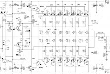
In my previous thread “A powerFULL amplifier named Dirty Harry” http://www.diyaudio.com/forums/showthread.php?s=&threadid=97566 I had presented the circuit and the layout diagram of the amplifier. In this new thread I will begin the presentation of his characteristics with base the SPICE simulation. Thus I hope becomes comprehensible the value of SPICE simulation. For beginning they are presented the named Operating Points in Volts (referred to ground) in certain critical points of circuit. As the voltages they are obviously presented in utmost various elements, it can easily be calculated the Voltage Drop across each component and thus the value of each current ( I ) that flows in each net.
To be continued.
Fotios Anagnostou
To be continued.
Fotios Anagnostou
Attachments
Fotios,
That is an interesting circuit. Thanks for presenting your work. I had a quick look at the thread you mentioned but could not see what output power you expect or whether it is Class A or B. Did you do the Spice model before or after the main development work?
That is an interesting circuit. Thanks for presenting your work. I had a quick look at the thread you mentioned but could not see what output power you expect or whether it is Class A or B. Did you do the Spice model before or after the main development work?
Looks like Class AB. The frontend looks like Self's Blameless, with a triple darlington output a la Leach.
"I know what you're thinkin', punk"
"I know what you're thinkin', punk"
Dear consort_ee_um from the supply voltage of amplifier you can make an approximate calculation of his output power. We have therefore symmetrical supply voltage of +/-82Volts that is 164Vp-p and thus 82Vpeak. For a given output load (clear resistive!) of 8Ù and if we suppose that we have one ideal supply unit of this voltage we can calculate for maximum current of 8Apeak (for greater current will be burned the fuse of 8A) that we have voltage drop of V =I.R = 8A X 0,33Ù = 2,64V at the emitter resistor of 0,33Ù. Consequently they remain 82V-2,64V = 79,36Vpeak. We have also voltage drop across the output transistor of 1,4V approximately thus remain 79,36-1,4 = 77,96Vpeak. In RMS the voltage applied across the load is Vrms = Vp/1,414 = 55,12Vrms. This corresponds with power at 8Ù: Prms = V2/R = 380Wrms in ideal state. Unfortunately in the practice, we cannot close in a box a power transformer i.e. 4 KVA because his size. Thus the usual transformer is of order of 1KVA (KilloVoltAmpere and not in Watts because the inductance of transformer imports the parameter cosö between current and voltage) shared in the two channels. This i see at least for 30 years where i deal with professional audio amplifiers. In my construction, i use separate transformers of 500KVA for each channel. Thus in the measurements that i made in the practice, specifically in signals of frequency under 100Hz where the time constant increases and the transformer should sustain a constant current for 10 to 50 msec the voltage decreases about 70 Vpeak in a output load of 8Ù. Thus the greater clean output power from 20 to 20000 Hz it is calculated in 300Wrms/8Ù and 500Wrms/4Ù in reality. I would want to point out a mistake that make many people; they appreciate that as long as more output semiconductors includes an amplifier, so much greater output power it can gives. In the practice the power is measured with base the supply voltage and the power of transformer. We put a lot of semiconductors because it should foresee a maximum current of 2A through each one. If you see for example the technical data of Motorola for the MJ15024 it reports Vce=250V and Ic=16A while in curve of SOA it reports 2A @ 80V 100% tested. This takes into account the designer, and in particular it calculates as maximum current 1,5A per output device when Vce exceeds 80V. This calculation for maximum current 8A gives 8/1,5=5,33 output devices, thus 6 devices per rail and total 12 devices in output. These to us are sure as we do not give special orders in Motorola for selected devices with the same beta (hfe). So much regularly it would be supposed I had placed in the amplifier; because the excess space of heatshink i put finally 14 output devices. Thus if I increase the supply voltage at +/- 86 Volts and with a transformer of 600KVA i can without fear take a output power of 350 Wrms from 20 to 20000 Hz.consort_ee_um said:Fotios,
That is an interesting circuit. Thanks for presenting your work. I had a quick look at the thread you mentioned but could not see what output power you expect or whether it is Class A or B. Did you do the Spice model before or after the main development work?
For your next question, as rightly observed Jaycee, the amplifier is biased in class B and with idle current of 20mA per output device it is finally classified in the fake? class AB. Indeed have read the book of Douglas Self and I liked a lot the topology emitter follower at the Voltage Amplifier Stage because she is simpler than usual cascode that I used before. Thus it included in my circuit. As long as for the SPICE simulation, it should you know that it does not draw from alone circuits. Yes, I used it previously the final construction to appreciate roughly the quality, and afterwards the completion of construction to calculate values of resistors so that I achieve the currents that I wanted in the various nets. If is precise the SPICE simulation? I can confirm this only for circuits of small size. For a circuit as large as the Dirty Harry loses his precision enough, because it supposes that all the semiconductors are identical with the SPICE models that includes while in the practice these deviate from ideal, a natural thing at process of production. In the calculation of voltages marked in the nets he is precise at 90% i can say, hence he is precious aid. You imagine how much difficult (and dangerous with so large supply voltage) it would be you change resistors continuously in the PCB until you achieve the currents that you want.
Fotios,
Thanks for the detailed reply. You made my day! I like the idea of using 2 transformers because the rectifier and capacitor ripple currents with 1 big transformer would be embarrassing!
Thanks for the detailed reply. You made my day! I like the idea of using 2 transformers because the rectifier and capacitor ripple currents with 1 big transformer would be embarrassing!
This is a correct choise. The use of 2 transformers not offers only flexibility in the assembly of unit, but also the benefit of the reduction of noise caused by the ground loop. Keep absoloutelly seperate the ground nodes between the 2 transformers and the usuall buzz noise it will disappears. Thanks for the good words and stay tuned for further informations about the practice. Good luck in your construction.consort_ee_um said:Fotios,
Thanks for the detailed reply. You made my day! I like the idea of using 2 transformers because the rectifier and capacitor ripple currents with 1 big transformer would be embarrassing!
- Status
- Not open for further replies.
- Home
- Amplifiers
- Solid State
- SPICE model of Dirty Harry