How do you really want to use them?
Take NI Multisim, CP-650 datasheet and you’ll be able to create +-realistic model.
SPICE Model Creation from User Data | Online Documentation for Altium Products
Take NI Multisim, CP-650 datasheet and you’ll be able to create +-realistic model.
SPICE Model Creation from User Data | Online Documentation for Altium Products
Last edited:
The plan is to use 5 per channel to make a fleawatt stereo amp.
Never heard of NI Multisim, I'll look it up, cheers.
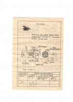
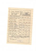
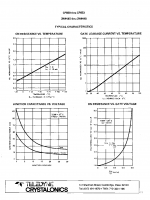
I found the CP650 datasheet, never thought to look at it, spacibo.
Never heard of NI Multisim, I'll look it up, cheers.
I found the CP650 datasheet, never thought to look at it, spacibo.
Attachments

Last edited:
The plan is to use 5 per channel to make a fleawatt stereo amp.
Ok.
What gain? Or just follower?
Maybe better to pick cheap LU1010 at ebay?
spacibo
Nothing for aka «не за что».
I've already got quite a few LD1010Ds, I'm currently building a small amp using 5 per channel:
Simple Class A Amp using JFET Output Devices
I obtained 10pcs of the KP903A from a friend in Hungary, traded them for some Motorola OC35 Germanium TO-3 he wanted for some reason.
I have no idea what topology of design to make with the KP903, it's just a case of I have them and would like to use them, so I'm open to any and all suggestions.
Hi Ian,... I'm open to any and all suggestions.
I designed this one for Pawel
IansEchoAmp - Google Drive
and simulated it for proof of concept, distortion and power dissipation checks. I haven't made one.
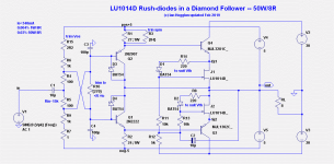
It uses a floating +/-5V supply. It can be changed to a stage with gain by grounding the 5V centre rail and removing the ground of the 40V center rail (ie floating 40V rails). The Area=2 means two in parallel for 100W. For a 50W version use only one.
I can share the LTspice file if you want, also my LU1014 model I created using the VDMOS for a better fit to the datasheet (you can see how I added param Mu=10 using a VCVS).
See
.model kp903a njf vto=-6 beta=13m lambda=10m rs=0.36 rd=0.3 is=1n cgd=80p cgs=80p kf=3.e-17 af=0.5 b=1 mfg=ussr
.model kp903a njf vto=-6 beta=13m lambda=10m rs=0.36 rd=0.3 is=1n cgd=80p cgs=80p kf=3.e-17 af=0.5 b=1 mfg=ussr
Kp903
Kp903 is an amazing device ! I have tested 2 dozens in various configurations and it is truly superb, especially in line amplifier duty. But there is a catch, unfortunately part to part parameter variation is huge by any standards! My fets were bought from 3 different suppliers and parameters were off by a 50%! This makes the parts unusable. Though for some applications you can find 2-3 matching pairs for a line amplifier let’s say.
Kp903 is an amazing device ! I have tested 2 dozens in various configurations and it is truly superb, especially in line amplifier duty. But there is a catch, unfortunately part to part parameter variation is huge by any standards! My fets were bought from 3 different suppliers and parameters were off by a 50%! This makes the parts unusable. Though for some applications you can find 2-3 matching pairs for a line amplifier let’s say.
Hi folks
Thanks for the help, sorry it took me so long to respond, but my parents are ill and I've been looking after them so not had any spare time to devote to hobbies.
I was thinking of building a low power amplifier using my KP903s, 5 per channel as output devices.
I've got a few other projects to finish off first though, so I'll not actually build itfor a little while yet, right now I need to figure out what design to use.
I shall study Ian's Echo Amp, sounds rather intriguing, so thanks for sharing that.
Updated LU1014D model and 50W amp
Thanks for your interest! It is an unusual design. No global feedback.
Like any follower it needs a high voltage driver amp (30V peak or 20V rms).
The floating 5W supplies may be off-putting to many but...
I'm thinking a 2W +/-5V DC/DC for each ch would then allow 1 transformer for a 2 ch amp.
The 5V rails need to be regulated.
Attached is an updated design with LTspice simulation files.
My updated LU1014D subcircuit model can be found in this file.
BTW I don't have any LU1014D's yet to try it - I'll get some in next order.
Cheers,
Hi Ian,...I need to figure out what design to use.
I shall study Ian's Echo Amp, sounds rather intriguing, so thanks for sharing that.
Thanks for your interest! It is an unusual design. No global feedback.
Like any follower it needs a high voltage driver amp (30V peak or 20V rms).
The floating 5W supplies may be off-putting to many but...
I'm thinking a 2W +/-5V DC/DC for each ch would then allow 1 transformer for a 2 ch amp.
The 5V rails need to be regulated.
Attached is an updated design with LTspice simulation files.
My updated LU1014D subcircuit model can be found in this file.
BTW I don't have any LU1014D's yet to try it - I'll get some in next order.
Cheers,
Attachments
Thanks Ian.
I'm, still laid up with an antibiotic resistant infection, so it will be a little while before I can get to work on this, but I will do... eventually.
Much appreciate your help.
I'm, still laid up with an antibiotic resistant infection, so it will be a little while before I can get to work on this, but I will do... eventually.
Much appreciate your help.
BTW, I happen to have 10 pairs of Sanken C3263/A1294, could I substitute these for the MJL3281/MJL1302?
Hi Ian,
2SC3263/A1294 should be fine.
I have done some further design work ready for a bench trial. I have written a paper explaining the options for making a practical 50W or 100W using this arrangement. It is here IansEchoAmp - Google Drive
It will take a month or two before I can try this amp.
I wasn't aware the LU1014D had gone extinct 😱 I intend to use MOSFET's instead of LU1014 jFET to try it. Are you still interested if there are no longer jFET's in the amp?
You can still use the LU1014D's but I won't be able to verify the circuit first. You will only have simulations modification to go by if you make one.
Cheers,
Hi Ian
Sorry for the slow response, just got out of hospital, not been well.
Your project sounds very interesting, be it JFETs or MOSFETs, so please keep me informed! 🙂
Sorry for the slow response, just got out of hospital, not been well.
Your project sounds very interesting, be it JFETs or MOSFETs, so please keep me informed! 🙂
- Status
- Not open for further replies.
- Home
- Design & Build
- Software Tools
- Spice model for Russian KP903A JFET?