Dear all,
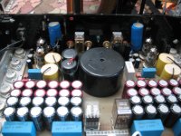
Recently a Sphinx amplifier entered my workshop. It is a model 14 with 2 tubes and Mosfet's in the amplifier stage. These are the 2SJ50 and the 2SK135, very famous in Holland in the 80's when Elektuur came out with the Cresendo amplifier for diy purposes and these mosfet's.
The tubes are ECC88
The reputation of the 14 is not so good. Later, Sphinx made a rebuild which was more reliable. The biggest problem is the design of the PCB and the power supply for the tubes. But the sound is fantastic!
Well, my question, does anybody have a diagram for this amp?
Thanks in advance for the help and i'll keep you folks posted.
Ah, the problem is loud hum and oscillation.
Attachments
A diagram seems to be impossible to find even from employees of the company.
I redesigned the hv power supply to a simple follower with zener diodes and it seems to work.
Had a look for all elcaps on the board, because the unit runs hot.
Oscillation problem could be solved by substituting ECC88 by ECC85 as second tube.
I redesigned the hv power supply to a simple follower with zener diodes and it seems to work.
Had a look for all elcaps on the board, because the unit runs hot.
Oscillation problem could be solved by substituting ECC88 by ECC85 as second tube.
Sphinx Project Fourteen diagram
Finally I received a diagram from a late owner of the company.
This shows a single channel of the stereo amp. Not sure it applies to
all versions of the amp if there are any.
Parts designations are mostly missing. At least I think it is fairly accurate.
The supply is not described here - the tube hv supply causes problems
frequently.
Attachments
Thanks for the share!
If you don't mind me asking, what do Q2 and V2B do? CCS loaded emitter follower? What is with C10-C12-C14? Some kind of "impedance booster" for the V2B CCS? I assume V2A is another gain stage?
If you don't mind me asking, what do Q2 and V2B do? CCS loaded emitter follower? What is with C10-C12-C14? Some kind of "impedance booster" for the V2B CCS? I assume V2A is another gain stage?
Thank you for your question,
this thread was not for discussion of the circuit, the repair issue of P14 itself being enough of problems.
But this may be a practical example of a tube-transistor hybrid power amp, whatever this may be good
for, and I read of good sound quality of this particular item (anyway we will not discuss sound aspects
here, just fix the amp).
stage, it is sort of push-pull and push-pull driven by phase splitting action of V2A and its plate and
cathode resistors. Would be interesting to know the values of R20,22 and R24,26, but the unit is no
longer in my workshop (in a classical phase splitter plate and cathode resistors would be the same).
So this is not a CCS loaded follower but form of a "totem pole" output and is not seen frequently.
You can imagine a triode in place of T2 with only small change of properties, mainly increased output
impedance.
referenced where the cathode of V2A is at positive dc level. V2A plate is dc coupled to T2 base.
In other words: T2 base is driven by V2A plate and V2B grid is driven by V2A cathode.
is greater than R24,26, but as said before I don't know the actual values of these resistors.
By the way the Mosfet output transistors are of the Hitachi J49, K134 etc. style.
this thread was not for discussion of the circuit, the repair issue of P14 itself being enough of problems.
But this may be a practical example of a tube-transistor hybrid power amp, whatever this may be good
for, and I read of good sound quality of this particular item (anyway we will not discuss sound aspects
here, just fix the amp).
I don't see Q2 in this circuit, but if you talk about T2 and V2B this is indeed an unusual driver outputIf you don't mind me asking, what do Q2 and V2B do? CCS loaded emitter follower?
stage, it is sort of push-pull and push-pull driven by phase splitting action of V2A and its plate and
cathode resistors. Would be interesting to know the values of R20,22 and R24,26, but the unit is no
longer in my workshop (in a classical phase splitter plate and cathode resistors would be the same).
So this is not a CCS loaded follower but form of a "totem pole" output and is not seen frequently.
You can imagine a triode in place of T2 with only small change of properties, mainly increased output
impedance.
C10,12,14 are required as coupling cap to this output stage, because the grid of V2B is groundWhat is with C10-C12-C14? Some kind of "impedance booster" for the V2B CCS?
referenced where the cathode of V2A is at positive dc level. V2A plate is dc coupled to T2 base.
In other words: T2 base is driven by V2A plate and V2B grid is driven by V2A cathode.
In my view V2A acts as phase splitter, the gain may be 1 or more than 1 at the plate if R20,22I assume V2A is another gain stage?
is greater than R24,26, but as said before I don't know the actual values of these resistors.
By the way the Mosfet output transistors are of the Hitachi J49, K134 etc. style.
Found some parts values in my notes, see the diagram in post 5.
C2 220p
R2 1k5
R4 22k
R8 8k2
R12 1k8
R14 68k
R18 100
R20 110k
R22 110k
T2 BF759
More are not available at the moment.
C2 220p
R2 1k5
R4 22k
R8 8k2
R12 1k8
R14 68k
R18 100
R20 110k
R22 110k
T2 BF759
More are not available at the moment.
A thread in a nederlands forum for dutch speaking people :
forum.zelfbouwaudio.nl • Toon onderwerp - Help! sphinx project 14 overleden Help!
forum.zelfbouwaudio.nl • Toon onderwerp - Help! sphinx project 14 overleden Help!
In post 2 of this thread
https://www.diyaudio.com/community/...-manual-will-be-rewarded.344189/#post-5964391
you can find a "Service manual" Sphinx Project PJ14 .
Is the storage in Google drive safe for the future ?
https://www.diyaudio.com/community/...-manual-will-be-rewarded.344189/#post-5964391
you can find a "Service manual" Sphinx Project PJ14 .
Is the storage in Google drive safe for the future ?
- Home
- Amplifiers
- Tubes / Valves
- Sphinx Project Fourteen help wanted