Having never done this before, I wanted to run my plans by you guys and see if I'm on the right track.
I'll feed the F3 with a HP339A's oscillator.
The output will be into a Steinberg UR12 -> USB -> MacBook -> SignalScope.
The UR12's high-Z input accepts -35 to +4.5dBV. I make that to be 0 to 1.68Vrms.
I'll get more bits out of the ADC if I'm at the high end of that range, but I don't want to let the smoke out either. So let's call max-input 1.5V.
I assume I want to feed the F3 to a dummy load, and tap the Steinberg off an appropriate point?
So if I used a 0R68 + 1R3 + 2R + 2R + 2R (all 10 watt) I'd have about 8 ohms.
15w output into that would be 11V. That's RMS (not p2p), right?
Taking from either side of the 0R68 would give me 0.94V at full output.
Taking from the 0R68 to the 1R3 would give me 1.5V at 4.5 watts.
Taking from the 0R68 to the first 2R would give me 1.125 watts.
Those seem like reasonable points to take measurements. (The 0R68 will also work for the F5 at about 1.21V.)
Feedback appreciated.
Cheers,
Jeff.
Hi Jeff
I'm not sure if this will be any help, but it may offer something useful.
http://www.vitalstates.org/diy/amplifiers/simple-thd-measurement.pdf
it's a bit long in the tooth now and I'm pretty sure I've used something more recently that involved a UR22 and ARTA...
I'm not sure if this will be any help, but it may offer something useful.
http://www.vitalstates.org/diy/amplifiers/simple-thd-measurement.pdf
it's a bit long in the tooth now and I'm pretty sure I've used something more recently that involved a UR22 and ARTA...
Thanks, Zen Mod and VitalStates. The document was very interesting, particularly in putting the voltage divider after the dummy load (whereas in my proposal they are one-and-the-same).
Building the divider AS the load in an interesting idea. It offers the lowest possible source impedance for the meter.
OTOH, the dummy load runs hot. Especially when working above the 15 Watt level. A couple hundred Watts of dummy is expensive. We tend to buy them barely big enough to stand the heat. When worked HOT the resistance will change. Now, it may hardly matter if the load is 7.9r or 8.1r. However if you are doing precise voltages, the division ratio can change from cold to hot. Especially when you stack different values of the same power rating. Different values will dissipate different powers. Maybe 5W in each 2r and 2W in the 0.7r. So different temperatures and different drifts.
And you don't need sub-Ohm source impedance for your metering.
So we usually go for big low-price dummies and select higher value more-stable precision parts for a separate divider.
Still, the combination load and divider is a clever idea.
If you're using a computer sound card for your FFT analysis, building one of Pete Millett's interfaces may be a good investment: Soundcard Interface
If you'd rather go with a voltage divider, I suggest using a pair of metal film resistors for the job. You don't want the voltage divider to introduce distortion.
Tom
If you'd rather go with a voltage divider, I suggest using a pair of metal film resistors for the job. You don't want the voltage divider to introduce distortion.
Tom
Another disadvantage of the all-in-one-load is that the voltage dividers don't give even scale multipliers. While I'm currently just interested in relative harmonics, I can't rule out wanting to measure absolute values in the future.
Pete Millett's interface is really cool, but I wouldn't be using most of it because I'm running a mic interface (with no output).
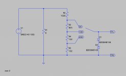
However, there are some features I might steal, such as the DC blockers on the input and the diode clipping.
Speaking of which, since my version is passive (and has no voltage references), I'd need to use two opposing zeners for clipping. Those won't inject excess noise below the clipping limit, will they?
Pete Millett's interface is really cool, but I wouldn't be using most of it because I'm running a mic interface (with no output).
However, there are some features I might steal, such as the DC blockers on the input and the diode clipping.
Speaking of which, since my version is passive (and has no voltage references), I'd need to use two opposing zeners for clipping. Those won't inject excess noise below the clipping limit, will they?
- Status
- Not open for further replies.
- Home
- Amplifiers
- Pass Labs
- Spectral analysis of an F3