I understand the concept and I can follow the designs given by programs which provide simulation of two identical speakers in series. But there is no program that I have found which can simulate two different speakers in series.
What would happen (in theory and practice) to two speakers with different t/s parameters? What would I expect to hear? Testing the speakers after installation with a microphone is not an option since they are not available to me.
Any ideas? Thanks in advance.
What would happen (in theory and practice) to two speakers with different t/s parameters? What would I expect to hear? Testing the speakers after installation with a microphone is not an option since they are not available to me.
Any ideas? Thanks in advance.
Thanks for your response. Please explain. On what do you base your opinion?
The voltage to either driver is undefined if in series since the impedance curves differ.
The drivers would also interact acoustically if they are in the same chamber.
As above, it's complicated as the impedance of each driver acts as a voltage divider and that determines how each driver gets "equalised".
When you have two identical drivers, at every frequency the impedance is identical so at every frequency they each get half the voltage or -6dB.
When you have two different drivers at say 50hz, driver A might be 5ohms and driver B 15ohms. Driver A will receive 25% of the voltage (-12db) and driver B 75% of the voltage (-3db). At 80hz driver A might be 20ohms and driver B 5ohms so it will be the opposite. This will give you a rough response from each driver, particularly around each drivers resonamt frequency where the impedance swings wildly.
All the T / S parameters of each controller, the different phases generated, etc, etc., everything will interfere, against each other.
It does not seem logical to develop much theory about something that does not start from a solid foundation, it is like asking why you cannot use a wheel that is totally different from the others in a car.
Waste of time and mental energy.
It does not seem logical to develop much theory about something that does not start from a solid foundation, it is like asking why you cannot use a wheel that is totally different from the others in a car.
Waste of time and mental energy.
It would still be a problem even if the 2 different drivers were in parallel. Just not a good idea.
Last edited:
The voltage to either driver is undefined if in series since the impedance curves differ.
The drivers would also interact acoustically if they are in the same chamber.
And what if they were in different chambers?
As above, it's complicated as the impedance of each driver acts as a voltage divider and that determines how each driver gets "equalised".
When you have two identical drivers, at every frequency the impedance is identical so at every frequency they each get half the voltage or -6dB.
When you have two different drivers at say 50hz, driver A might be 5ohms and driver B 15ohms. Driver A will receive 25% of the voltage (-12db) and driver B 75% of the voltage (-3db). At 80hz driver A might be 20ohms and driver B 5ohms so it will be the opposite. This will give you a rough response from each driver, particularly around each drivers resonamt frequency where the impedance swings wildly.
thanks. this was very helpful. the idea that they would have different voltages at the same frequency and not something that could be "balanced out " makes sense.
With amplifiers when you put two caps in series you have put a small resistor on each cap so each cap gets the same voltage. It sounds like you are saying that there is no way to do this with speakers of different t/s parameters.
And what if they were in different chambers?
If each has its own (parallel connection) crossover, then it could be designed.
So I guess the next question is: given that two different drivers won't work well with each other, how far off do two (or three, etc) have to be from each other before they interfere? Is this a real problem with line arrays?
If each has its own (parallel connection) crossover, then it could be designed.
Interesting. Please explain. Under these circumstances how would the amp "see" the drivers? Would the impedances of each driver be added as in series?
Is this a real problem with line arrays?
It's critical to use identical drivers, for a line array to work properly.
Interesting. Please explain. Under these circumstances how would the amp "see" the drivers?
Would the impedances of each driver be added as in series?
The amplifier is a voltage source, so to avoid interaction between the two different drivers,
the drivers would have to be in parallel.
If the drivers also each have separate passive crossover networks, the networks would have to be of the
parallel type (where each network separately connects to the amplifier terminals), again to avoid interaction.
It's critical to use identical drivers, for a line array to work properly.
How far off can they be and still work properly? And does this apply only to the impedance of each driver or do all the other parameters also have to be identical?
The amplifier is a voltage source, so to avoid interaction between the two different drivers,
the drivers would have to be in parallel.
If the drivers also each have separate passive crossover networks, the networks would have to be of the
parallel type (where each network separately connects to the amplifier terminals), again to avoid interaction.
So even by this design it is impossible for the amp to see the drivers in series; it will always see them as separate; therefore there is no way, no configuration that would allow the amp to see them in series thereby getting the benefits of series speakers without significant problems. Correct?
Series filters were in the Vogue in the 1970's.
Tandberg speakers used them a lot.
A piece of Windows software that doesn't bat an eyelid at series designs is: Software | Visaton
I became fascinated by this this Visaton design called the WLM La Scala.
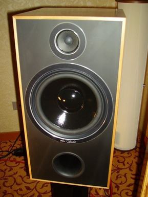
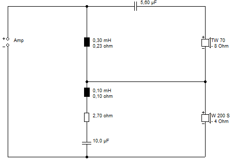
Generally speaking, series filter designs rely on drivers that play happily together. TBH, not many do. But when it does work, it works beautifully! 😀
I built this speaker with the 8 ohm version of the midbass driver and a parallel filter as a sort of homage:
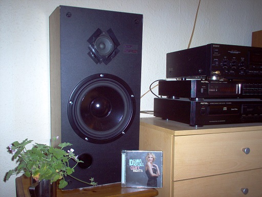
Very good, IMO.
Tandberg speakers used them a lot.
A piece of Windows software that doesn't bat an eyelid at series designs is: Software | Visaton
I became fascinated by this this Visaton design called the WLM La Scala.
Generally speaking, series filter designs rely on drivers that play happily together. TBH, not many do. But when it does work, it works beautifully! 😀
I built this speaker with the 8 ohm version of the midbass driver and a parallel filter as a sort of homage:
Very good, IMO.
So even by this design it is impossible for the amp to see the drivers in series; it will always see them as separate; therefore there is no way, no configuration that would allow the amp to see them in series thereby getting the benefits of series speakers without significant problems. Correct?
Probably there's no way to do that.
Last edited:
How far off can they be and still work properly? And does this apply only to the impedance of each
driver or do all the other parameters also have to be identical?
The drivers in a line array should all be identical in all respects, driven identically.
A line array would normally have drivers in a series-parallel connection to make
a reasonable total impedance, and for each driver to have the same drive voltage.
For example, three series groups of three in parallel. That would result in the same
impedance as a single driver, with each driver getting 1/3 of the input voltage.
Have you tried Xsim? It is a crossover simulator, but you can place different drivers in series and get combined frequency response and impedance. You need to have .frd and .zma files for the drivers, but even if you do not have these for your own drivers you can use other drivers to get an idea of the effects. Dayton has that info for nearly all of their own drivers.
The impedance curves of different drivers in series will interact to change the frequency response of each. The greater the mismatch in the impedance curves the larger the effect will be.
Line arrays are a special case, since the drivers in a line will be of the same model. Ideally they would be identical in all respects, but manufacturing tolerances make this unrealistic. Over most of the frequency range this variance might typically amount to just a fraction of a decibel difference. But if the drivers have a wide variance in Fs this has the potential for a bigger problem. Suppose most of the drivers have an Fs of 50 Hz, but one in the line is at 40 Hz. That driver will produce a greater share of the output at 40Hz, and would reach its excursion limit before the others in the line. Connecting multiple drivers together in series-parallel (such as the 3-by-3 arrangement mentioned above) can help mitigate this by averaging the impedances together in the parallel groups. Also, a resistor in parallel with each group will lower the impedance peak, though it will also lower the overall impedance and waste some power. I might use such a resistor if I had just a few drivers (the woofer/subwoofer section) on an open baffle and I need to ensure equal excursion near Fs.
- Home
- Loudspeakers
- Multi-Way
- speakers in series