Hi All
I have a pair of small Mission bookshelf speakers with one DEAD. Absolutely no sound when connected to amp. Tried switching with the other one that works, same result - nothing came out.
Is this problem common? I have a feeling that both the tweeter and woofer dead at the same time is quite seldom. Is the cross-over the culprit or something else?
I'd like to fix it myself. Any solutions or ideas would be welcome.
Thanks.
patknk939 said:Hi All
Tried switching with the other one that works, same result - nothing came out.
Thanks.
So when you switched how did you switch? Did you put the "dead" cabinet on the live cabinet amp channel or the live cabinet on the "dead" amp channel? Or to put it another way.....does the problem move with the speaker or does it stay with the amp channel?
Re: Re: Speaker repair
I don't think wiring (I assume this refers to speaker cabling) is the problem because the problem speakers were tested by connecting to a pair of working speakers. The problem moves with the speaker when switched between channels. I did take out the tweeter/woofer and saw the crossover at the back of the cabinet but hadn't taken it out and not sure there's a circuit breaker or fuse.
John L said:Check your wiring first, then the crossover. Incidentially, does the speaker have a fuse or circuit breaker?
sauuuuuce said:
So when you switched how did you switch? Did you put the "dead" cabinet on the live cabinet amp channel or the live cabinet on the "dead" amp channel? Or to put it another way.....does the problem move with the speaker or does it stay with the amp channel?
I don't think wiring (I assume this refers to speaker cabling) is the problem because the problem speakers were tested by connecting to a pair of working speakers. The problem moves with the speaker when switched between channels. I did take out the tweeter/woofer and saw the crossover at the back of the cabinet but hadn't taken it out and not sure there's a circuit breaker or fuse.
Ok, if you know for certain that the problem is definately related to the speaker, not the cable or the amp, then you will need to pop the lid to the speaker, or remove the main driver so you can look in at the inner wiring.
You need to see if the wiring to the terminal, is sound. I find it highly unlikely that both the tweet and woofer would be gone all at the same time, and not have the other channel do same to the other speaker.
I still think that the odds are a loose connection. I could be wrong though.
You need to see if the wiring to the terminal, is sound. I find it highly unlikely that both the tweet and woofer would be gone all at the same time, and not have the other channel do same to the other speaker.
I still think that the odds are a loose connection. I could be wrong though.
Hi,
A quick and cheap way of establishing if internal wiring and component continuity exists, is to briefly connect a single cell battery across the input terminals of the speaker. Just touch the terminals of the speaker with a battery using a piece of suitable wire to make the connection, for a second or so at a time, on and off.
So long as it is a single cell giving merely 1.5 or maybe 1.6V DC, there will be no harm to anything (except an active speaker, of course), and on making the connection briefly, there should be an obvious 'click' or 'pop' heard each time. Also, you should be able to see most diaphragms move briefly inwards or outwards when the battery is connected, and this is a good way of checking the 'polarity' of the driver wiring, although with the very limited movement of most tweeter diaphragms, this is not always easy to see.
If nothing at all visually or aurally happens when you try this out, either both voice coils have burned out or similar (which is less likely), or something has become open circuit within the enclosure which prevents the signals from reaching the drivers.
Regards,
Hi Bob
As suggested, I've just tested both the tweeter and the woofer with a battery. Both have "click" when connected to the battery. This proves that both in fact work. Therefore, the problem seems to come from the cross-over. I've also checked the wiring and the connection to the x-over, they are not loose. At the same time, I've taken the x-over out from the enclosure. The x-over just made up of 2 coils, two 5W 3.3ohm JF resistors, two 12uF 50V capacitors and one 4.7uF 50V capacitor. So, how am I going to test where the problem is? Thanks for your advice.
Pat
If both speakers are working, and you think it is the crossover, you are faced with either a completely fried crossover, where both circuits are fried, or the wiring leading to, or from, the crossover is shorted.
If the crossover is not fried, then the fact that both speakers do not work strongly suggests that only wiring that is used by Both drivers has a short. Just check the circuit up to the point where the line branches out to the high and low frequency drivers. If not that, then I would suggest a complete breakdown.
If the crossover is not fried, then the fact that both speakers do not work strongly suggests that only wiring that is used by Both drivers has a short. Just check the circuit up to the point where the line branches out to the high and low frequency drivers. If not that, then I would suggest a complete breakdown.
Hi Pat,
That is a good start but are you saying that you don't get any clicks/pops if you connect the same battery across the input terminals to the speaker?
Even though the DC battery voltage will probably be 'blocked' by some intervening capacitors (at least in the tweeter circuit, anyway), you should still hear a similar or at least some noise when you touch the battery on and off the entire speaker unit's input terminals.
If doing this test, it is absolutely quiet, then you have isolated the problem to somewhere between the input terminals and the drive-units, which basically means in the x'over itself, or any connecting wiring between x'over and input (most likely), or possibly between the x'over and the drivers. As John L suggests, this latter situation is much less likely as there will be separate wiring from the x'over to each driver, and it would be rather unlikely that both sets of wires would have failed at the same time.
If it doesn't seem like there is an obvious problem with the 'shared' wiring from input to the x'over, then it will take a bit of work to identify which x'over component(s) is/ are the culprits here. In my experience, something going completely 'dead' as you suggest, is more likely to be a failed solder-joint or similar, as although individual components will sometimes fail, often (mostly?) they will still pass some sounds, albeit distorted or reduced in amplitude.
Do you have access to any test gear like maybe even a cheap multimeter, and are you able to solder and unsolder various parts in the crossover? If not, and you do establish that the problem is within the x'over itself, then I think you will need some help with this from a local technician, unfortunately.
Regards,
Hi Bob. I've done the test of touching the battery on and off the input terminals of the speaker. It's absolutely quiet. No click nor pop from both drivers. I have both needle and digital multimeters. I'm quite comfortable with soldering and de-soldering. I appreciate your further advice. Thanks.
Regards
Pat
Regards
Pat
Hi Pat,
That's excellent, and I reckon we stand a good chance of resolving this problem now that you have confirmed this.
I assume that you have checked (or will firstly check) the continuity of each wire involved, both from the input terminals of the speakers to the x'over, and between the x'over and each driver. The readings here should be virtually zero Ohms, if you connect the meter's leads from one end of each individual wire to the other.
Whilst by no means essential, it would be helpful to see how these x'over parts are arranged. As there are so few components, can you draw out how the various connections are between the input terminals of the x'over, how each component is attached to the others, and finally where the outputs to the 2 drive units are in relation to this? i.e A schematic of the complete x'over.
If this isn't easy, what I suggest you do initially is to measure across each individual component in the crossover, and make a note of the DC resistance reading. Having done this, do the same with the other (good) speaker, and compare these with each other. Of course, if say you find that any component is completely open circuit (i.e. infinite resistance) in the bad x'over, then this will be where (or at least part of where) the problem lies, and there should be no need for any comparisons with the good x'over.
Personally, although I have several costly and very fancy and accurate multimeters in my tool kit, I find that a good old cheap analogue type (with a needle, as you mentioned) is much better for this diagnostic work, at least for some initial cursory checks.
You will find with caps for example that initially there will be a brief reading of sorts, which will rapidly change to (almost?) infinity, depending on the cap's value. With an analogue meter, you can readily watch the needle 'swing' from one end of the scale to the other (and try different resolution settings too), but with a digital meter, the change is too rapid for it to be displayed properly.
Reversing the meter across the cap and back again a few times, will enable you to see how this change in resistance occurs each time, and this can be compared with the known good cap from the other crossover. Unless you have a capacitance measuring facility (which I assume you haven't), this can indicate some worthwhile info on caps, especially if one has gone completely open circuit, whereupon there will be no reading at any time other than infinity. It will also indicate if the cap is internally shorted out, by showing virtually zero resistance, but in view of your symptoms here I don't think it is very likely that one bad cap would short out across both drivers, which would need to be the case from what you describe.
If any cap does show virtually zero resistance, it might be that it is in parallel with an inductor (coil) which you should be able to see, so this in itself is not a definitve test, but in such a x'over I think it is less likely that there would be caps and inductors in parallel, but this is something to bear in mind.
When doing this check on any caps, by reversing the meter connections over, each time you re-connect them you are charging the cap up briefly with the opposite polarity, but if there is no charging up happening at all (i.e no movement of the meter needle under any circumstances), then the cap is most likely broken internally.
For the resistors and the coils, you should see some steady readings which make sense and will be similar for both crossovers, except where a problem lies. Without knowing any more about the circuit layout, this is about as far as I think we should go for now. The coils should only show a fraction of an Ohm (probably less than 0.5 at a guess), but they should show continuity, of course, i.e. a definite and steady low-value reading.
Some components will almost certainly be in parallel with each other and the drive units, and this will affect some readings and if nothing obvious shows up with what I have suggested so far, it may be necessary, as the next step, to unsolder at least one end of certain components so that they can be measured individually, but let us first see what happens with the above suggestions.
Fortunately, with any stereo system where only one channel is bad, you have a good 'reference' to make comparisons with. Also, if the worst came to the worst, and you are still prepared to spend the time to save paying someone else to do this diagnositic work, you could systematically swap each component over (one at a time) from the bad to the good x'over or vice versa. This way, you are bound to discover which is the problem component, although this will be a 'last ditch' attempt, and I hope that we can discover the problem with a lot less involvement.
Regards,
Hi Bob
I tested the components on both cross-overs with multi-meter. Coils and resistors on both the good and the bad cross-overs show same reading, ie 0 ohm (needle of the meter swings all the way to the right). As for the caps, all of them also show similar readings, ranging from 5 to 10 ohm. So, there's no difference in their readings during the tests and thus it seems that the problem doesn't come from them.
I went back to test the continuity of the wires from the cross-over to the drivers. They showed 0 ohm and thus continuity is not broken.
Then I turned to test the wiring from speaker terminals (in this case, the +ve and -ve terminals on the cross-over circuit board, because they have now been separated from the speaker enclosures). First I contacted the +ve pole of the meter with the +ve terminal and tested all wires to the HF and LF drivers with the -ve pole of the meter. Afterwards, I reversed the meter poles and did the same test. During the tests to both the cross-overs, meter showed readings - either full swing to the right or short swing then back down.
However, when these tests were done on the -ve terminal, while the good cross-over showed reading, there's nothing from the bad cross-over. So, is the problem coming from the continuity between the speaker terminals and the cross-over?
In fact, I just discovered that there's a crack across the back of the bad cross-over circuit board. When I connected the multi-meter's poles between this crack and the speaker terminals on the board, reading showed up, ie needle swing all the way to 0 ohm. Is this actually the culprit? If yes, can I repair it by soldering the crack?
Appreciate your advice.
Regards
Pat
I tested the components on both cross-overs with multi-meter. Coils and resistors on both the good and the bad cross-overs show same reading, ie 0 ohm (needle of the meter swings all the way to the right). As for the caps, all of them also show similar readings, ranging from 5 to 10 ohm. So, there's no difference in their readings during the tests and thus it seems that the problem doesn't come from them.
I went back to test the continuity of the wires from the cross-over to the drivers. They showed 0 ohm and thus continuity is not broken.
Then I turned to test the wiring from speaker terminals (in this case, the +ve and -ve terminals on the cross-over circuit board, because they have now been separated from the speaker enclosures). First I contacted the +ve pole of the meter with the +ve terminal and tested all wires to the HF and LF drivers with the -ve pole of the meter. Afterwards, I reversed the meter poles and did the same test. During the tests to both the cross-overs, meter showed readings - either full swing to the right or short swing then back down.
However, when these tests were done on the -ve terminal, while the good cross-over showed reading, there's nothing from the bad cross-over. So, is the problem coming from the continuity between the speaker terminals and the cross-over?
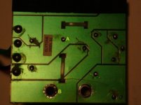
In fact, I just discovered that there's a crack across the back of the bad cross-over circuit board. When I connected the multi-meter's poles between this crack and the speaker terminals on the board, reading showed up, ie needle swing all the way to 0 ohm. Is this actually the culprit? If yes, can I repair it by soldering the crack?
Appreciate your advice.
Regards
Pat
Hi Pat,
Yes, this crack you mentioned is exactly the kind of damage that we are looking for here, and I would say that about 99% sure this will solve your problems when it is fixed.
As I have said all along, it is much more likely to be a break in continuity somewhere, as when caps etc. go bad, one usually hears some signal still, albeit at a lower level and possibly distorted etc.
A complete break in any track like this and in this location will prevent the entire signal from passing through to (or from) both drive-units (which accords with your symptoms), and it should be easy to fix. I don't wish to 'teach my grandmother to suck eggs' here, but in case you are not very familiar with such repairs, I hope that the following might be of some help.
Firstly, try to understand how this break has come about as you will be better to avoid it happening again, and now you have the chance to do something to prevent this. Usually, such breaks in tracks will be caused by flexing of the PCB, so you might wish to mount this more securely, or whatever. It could be caused by vibration from within the speaker cabinet, so anything you can do to reduced any flexing of the board when you replace it, will be of some help. There might be sufficient area around the edges of the PCB where there are no copper traces, and where some additional screw-holes could be drilled, but make certain that nothing is done to harm any of the copper traces.
When you come to solder across this break in the track, clean up the entire width of the track (removing the solder-mask, if there is any) by careful scraping or whatever, so that the copper trace is absolutely clean and shiny. You really should reinforce this break with something, and I would use some copper wire soldered across the broken joint. This wire is not critical in size but if the wire you have available is not very thick, use 2 or 3 pieces which will bridge across the joint and solder them side-by-side for some added strength.
Initially 'tin' (with some fresh solder) the ends of the traces where you will be soldering the added wire(s), and do the same 'tinning' with the piece(s) of wire to be used here so that all parts are evenly coated with some solder. Then lay the reinforcing wire(s) along the trace and hold it (them) down with something whilst you do the final soldering, or otherwise the wire will 'stick' to the soldering iron tip and move around. Almost anything other than metal and which won't readily melt with the heat would do here (you don't wish to solder this if it is metal as well!), but maybe the end of a spent matchstick or similar, and you could probably tape across the ends of this short stick if it is placed at right-angles across the piece(s) of wire. Then finally apply the soldering iron with a bit more solder on the tip to the entire joint until the solder forms a fillet beween the trace and the wire(s), and the job is done.
I have been doing this for many years and use needle-nose tweezers to position and hold the wire with one hand and the iron with the other, but for your first attempt I would try to tape something across the joint or you will probably get frustrated with the wire being pulled away when you think you have finished, with it sticking to the tip of the iron. Alternatively, maybe someone else could temporarily hold down the wire(s) for you with the end of a matchstick or similar while you effect the repair.
When not being very experienced at this job it is helpful to keep one hand free, as you can then also add a bit more solder whilst doing this (if it is needed) to end up with a good joint here, whereas otherwise you do need to judge how much 'pre-tinning' is needed so that when finished with heating the entire arrangement, the final result is good.
If you end up with a repaired joint which is mechanically quite strong here, it should be fine as far as the sound goes, but it doesn't need to be a great big 'gobbed-up' affair as this will be less good sonically. Merely soldering across such a joint might be OK in the short term but it will inevitably go bad again in time unless you have some reinforcement to hold everything together, and that is where some added wire will help a lot. Without knowing the size of track which is broken, I would say use a piece of wire about 1/2" long as a minimum, but if both sides of the track are suitably arranged, 3/4" would be better to give some overlap with the soldered joint.
I hope that this now solves your problem, and I will keep my fingers crossed for you. It is a bit too early yet to be self-congratulatory with this, but when you have solved this problem I am sure you will enjoy a sense of satisfaction that you have achieved this yourself.
Regards,
Hi Pat,
Now that I have seen what this looks like, yes you certainly could do what you now suggest, and this will probably be much easier for you. Maybe I should have suggested this before as an alternative, but I had no idea of the physical layout or how wide this particular trace is before seeing this pic.
You should use some substantail wire for this, though, and I would suggest ideally something of a similar gauge to your speaker wires, as this looks like it is the negative 'return' from both drivers which has broken. This trace will carry some quite high currents, but any wire of a similar gauge to your usual speaker wires will be OK, as this trace is only effectively an extension of these speaker wires, anyway.
Lastly, that will certainly be the cause of your problems, but I wonder how such a large crack across so much of the PCB can have happened?
Regards,
Hi Bob
Problem solved by soldered wire between A & B. I'm hearing them for the first time and reasonably good for its size (I got them from ebay and had one dead on arrival, but seller didn't agreed to accept return for refund). I'm still trying to figure out how this crack on the PCB had come about. Anyway, thank you for your advice and guidance throughout the repair. This is my first one and a satisfying one too. Thanks again.
Regards
Pat
Hi Pat,
Well, I'm very pleased to hear this good news, and that you are satisfied with the results.
Of course I didn't know before that these speakers were new to you, but being able to hear them now after fixing them up for yourself (and at no cost!) must be very satisfying.
You will soon be able to start up your own speaker repair workshop!")
Regards,
Well, I'm very pleased to hear this good news, and that you are satisfied with the results.
Of course I didn't know before that these speakers were new to you, but being able to hear them now after fixing them up for yourself (and at no cost!) must be very satisfying.
You will soon be able to start up your own speaker repair workshop!
Regards,
- Status
- This old topic is closed. If you want to reopen this topic, contact a moderator using the "Report Post" button.
- Home
- Loudspeakers
- Multi-Way
- Speaker repair