I'm servicing an old HK (770) amp from the 80's, replaced most of the caps and redone the solder joints but got another problem in return - now both speaker relays take about 5-10 seconds to turn off after switching the amplifier off.
Yet they always respond immediately if I press the speaker 1/2 buttons. It looks like the coils remain powered for too long, but what would cause this? C21/C22 value too high?
Yet they always respond immediately if I press the speaker 1/2 buttons. It looks like the coils remain powered for too long, but what would cause this? C21/C22 value too high?
Attachments
Last edited:
Will do, just disassembled the amp again and the values look correct, both are brand new Panasonic FC an FM caps.
The zeners will be the next suspects, the board was rather crusty so I've redone the solder joints, maybe something gave up on the way.
+
Checked the zeners, all good.
Can C1 have any influence on this behavior? I guess not, but still - Ive replaced it with a slightly higher value cap I had on stock, 0.047uF.
Last edited:
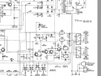
At power on C21 is charged quickly through D11 and R11. This then charges the delay circuit formed by R28 and C22, which then turns on Q4 and subsequently the relays.
At power off, C22 needs to be discharged rapidly to turn off Q4, and this is achieved through D12 (which becomes forward bypassed when C21 discharges) then discharges C22 through R12 and R13 to ground.
D12 may be faulty or there may be a dry joint or break in continuity in the connecting circuitry that discharges C22. Check D12 and the continuity from C21 through to the anode of D12, and the resistance from the cathode of D12 to ground.
Last edited:
Solder joints have been redone.
@johnmath,
Thank you, I will check everything that's mentioned.
D12 to ground is 3.16kOhm.
@johnmath,
Thank you, I will check everything that's mentioned.
D12 to ground is 3.16kOhm.
Last edited:
I've noticed something else aswell - the power LED now stays dimly lit after power off. It takes very long before it finally turns off.
Last edited:
Looks like the power LED is part of C22 discharge, R12,13 3.16k looks ok. Wondering if it could be leakage from C10, C14, rectifier. Test D2 bridge.
If the LED is dimly lit then some voltage is remaining on C22.
Q3 shorts C22 in the event of a fault to disconnect the speakers. Perhaps Q3 is faulty and leaking voltage through.
Also check D15 which is a zener. When the amp is on, D15 should be reverse biased with 5.1 volts across it. The purpose of D15 is to stop Q4 turning on until C22 has charged up to more than 5.1 volts.
Hi . Try to desokder d15 zener and test without it , relays must not click ,but power led turn off quick if amplifier turned off .
Can't see all the relevant circuitry but Q3 looks like it could be a detector for presence of AC.
I would look at the medium to high value resistors like R490 (is it, up at the top) and R28 (270k) plus any we can't see going off the bottom of the diagram to the base of Q3
I would look at the medium to high value resistors like R490 (is it, up at the top) and R28 (270k) plus any we can't see going off the bottom of the diagram to the base of Q3
I also measured the voltage over the power LED, 1.92V and after turning the amp off it very slowly drops. At 1.67V the relay disconnects. Then the voltage creeps up a bit and starts going down again very very slowly.
Unsoldered one leg of D15, relays don't come on anymore but the voltage stays.
I'm getting really curious about C1, I've noticed that with the power switch OFF the 1.5V drops very slowly. I then turned my variac to 0V and the 1.5V disappeared, turned it back to 220V - 1V on the LED and going up. Huh, the amp is OFF! I guess the 0.047 is new but leaky?
The relay drive worked fine before recap.
+
YES, it was C1. How crazy, I've unsoldered it for now and the operation is back to normal, after turnoff the voltage disappears immediately.
Is it because the 0.01uF is application critical or is the capacitor simply faulty?
Last edited:
The voltage across the LED should drop instantly, but I think what you are seeing there is a symptom, not directly to do with the cause of the fault. When the amp is turned off, C22 will feed the LED until it is discharged. C22 will also keep the relay on until it is discharged. The fact that C22 isn't being discharged quickly at turn off is the crux of the problem.
When you disconnect D15 there is nothing connected to the base of Q4 to turn it on, so the relay stays off.
If you think the 0.047 is implicated you can remove it and try with it not there. I think it is there to bypass diode switching noise from the rectifier bridge for the B2 rails.
The junction of R18, D15 and C22 should drop to 0 volts instantaneously when the power is switched off. If it doesn't you need to find what connected to the left hand side of D15 is faulty. If the voltage on C22 does drop instantly at turnoff the fault is somewhere in the circuit on the right hand side of D15 from Q4 to the relay.
Last edited:
C1 capacity increase makes transformer to produce some voltage even when power switch is off , so capacity is kinda critical,but you can also comnect capacitor in parallel to primary winding ,to absorb this current . Maybe try 0,1 uf, or return c1 value to 0,01uf as it was. Also check two resistors,associated with led ,for for open, they should shunt leakage current ,coming from secondary winding ,if amp is off .
Hi John,
Everything works correctly if I cut C1 out of circuit, voltages drop instantly after power off and so do the relays. Apparently the 0.01uF capacity is critical, did not expect that.
Everything works correctly if I cut C1 out of circuit, voltages drop instantly after power off and so do the relays. Apparently the 0.01uF capacity is critical, did not expect that.
Last edited:
Good, you've made progress. I'm not sure what's happening there; once the power is turned off, the transformer T2 that C1 is connected to is not energised. What happens if you put the old capacitor back?
Works fine with the original 0.01uF but it's that nasty exploding Rifa metalized paper cap and the case is already starting to crack.
Oops, my bad. I was mixing up C1 with C4, which is connected to D11, the rectifier for the relay circuit.
C1 is for arc suppression across the power switch to preserve the switch contacts and suppress a burst of electromagnetic radiation at switch-off. The value there is chosen quite carefully by the designer to prevent all sorts of weird behaviour. The old Rifas failed because of an unknown design issue with a breakdown mode. Capacitors for this application now have an updated MKP-X2 specification, so look for 0.01 of that type. In the meantime just leave it out and don't switch the amp on and off a lot to prevent damage to the power switch from arcing contacts.
Essentially because of the oversized value for C1 bypassing the power switch the supply is not completely turning off the transformers. I think the 0.047 value has a low enough impedance to allow enough current to flow in the primary to keep a small voltage on C21, which is preventing D12 from becoming forward biased to discharge C22.
- Home
- Amplifiers
- Solid State
- Speaker relays turn off too slow after poweroff