Hi guys,
I've just bought this cheap thing from Indonesia and I have a small boombox that I'm making where I'm using a 24VDC SMPS. Now this protector is said to run on 15-32V AC, which means I'd have to install a small transformer.
So my question is... would it be possible to feed it with the 24VDC from the SMPS? I see there are ONLY two diodes at the beginning of the circuit, which may mean it's not possible, but then there is a rectifier configuration elsewhere.
Alternatively, I could figure out where to take the unrectified electricity from the SMPS (there is no dedicated output) and feed it that?
I do not know much about speaker protectors so any help will be greatly appreciated!
Attachments


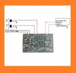
i saw 2 1N4002 diodes on the left of the second picture and another capacitor which suggests the input was a full wave rectifier to be used with center tapped transformer ... basically omit the 2 diodes and connect the 24v to the terminal of the capacitor with the correct polarity should get the circuit working ... so the ground plane will be the negative and the capacitor +ve terminal the positive volts
...terimakasih atas inputnya, dear neighbor! 🙂
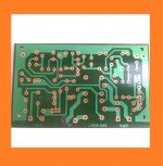
Yeah I was also looking at those diodes and wondering why there were only two... because the input is not CT: there are only two AC poles, as in the first pic. I flipped it to juxtapose it with the front.
Basically it's a half-wave rectifier, right? Not sure why they installed two diodes. Wasn't one enough?
Anyway your suggestion sounds great. I'll try and post the results.

The incoming AC is fed via a couple of 4002 diodes to a series pass transistor which output is regulated to 12v
Like this:
So the output from the emitter of TIP41C will be around 11.3V to power the rest of the circuit.
So feed your 24vdc to the 1000uF/35V cap over to the left of your last pics
Like this:
An externally hosted image should be here but it was not working when we last tested it.
So the output from the emitter of TIP41C will be around 11.3V to power the rest of the circuit.
So feed your 24vdc to the 1000uF/35V cap over to the left of your last pics