I soldered my first amplifiers in 70-ies.Some people want everything done for them…..
I coded my first computers in 80-ies.
Your posts make no sense - if you are tolerated, it is up to the mods.
The original design, if you look at the Gerber file, was designed to fit in the same footprint as a standard Tyco 16A relay with exactly the same pin outs. Adding a bridge and then dealing with the dissipation associated with some sort of current source drive on board is no trivial task.One could make the SSR idiot proof by full wave rectifying the input so it sends the current the right way through the photocouplers regardless of how the user connects it. Better than just a reverse protect diode because there would never be an error to correct. Works either way. And one could install a current source in the loop setting the LED current at 20mA, regardless of amp power supply voltage or if an auxiliary supply is there or not. No dropping resistor to calculate. Plug and play.
The DC blocking diode is a 5c solution that solves all the issues you raised.
I have inserted components the wrong way around many times in my 50 year electronics life. I too am an idiot.
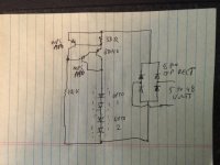
Hi Andrew,please have a look here.Eggburt, the post of mine above is incorrect, so let's do it again. The amp is 400W into 4 Ohms, so that is 10A RMS into the load at full power, 14A peak. With 8 pairs that is 1.75V peak across one of the emitter degen resistors (not both as I incorrectly stated in my earlier post). The opto emitter diode is typically 1.1V and we want 10 mA through that so (1.75V-1.1)/0.01 = 65 Ohms. Use 68 Ohms and adjust Rtrim per the earlier post.
I think something is wrong.
Thanks!
"The amp is 400W into 4 Ohms, so that is 10A RMS into the load at full power, 14A peak. With 8 pairs that is 1.75V peak across one of the emitter degen resistors"
How you calculare this?
Are the emitter resistors 1 Ohm?
Is it right?
PS yes you are right,i see now you have calculate for 1 Ohm emitter resistors(gfa 5800) post#208
Sorry!
How you calculare this?
Are the emitter resistors 1 Ohm?
Is it right?
PS yes you are right,i see now you have calculate for 1 Ohm emitter resistors(gfa 5800) post#208
Sorry!
Last edited:

Thank you Andrew for time spent on this. I have plenty of information now. This will make a nice winter project and I will most likely order a couple of your boards early next year. Have a great Holidays!
Andrew,i have another question.
D.C protection is a non latching function.
Is it a way to modify the circuit for latching d.c function?
I mean that a power interruption will be necessary for the circuit to return to its normal operation.
D.C protection is a non latching function.
Is it a way to modify the circuit for latching d.c function?
I mean that a power interruption will be necessary for the circuit to return to its normal operation.
Last edited:
Yes. There is a link on the board. IIRC if you leave it open it will latch, if linked it will automatically restart.
My personal preference would be to implement latching (i.e. manual reset) behaviour.There is a link on the board.
Speaker protection relay triggering should be an event that will not end up in a cycle during some sort of a party. 😉
I think the way we each share our own ideas can sometimes lead to confusion for those reading our circuit descriptions. I understood what you were writing, but I post diagrams now to help onlookers. It helps me, too.Some people want everything done for them…..
I was hoping I wouldnt have to draw it up and take a picture. All my CAD stuff is not on this machine. My idea was to make a universal (or semi universal with board stuffing options) SSR replacement for the big ice cube relays I used to use for speakers protection. In general they ARE large enough to reliably open when a 200-400 WPC amp heads for the 80 volt rail. Used them in the field for decades back in my DJ days (the amps were home made, or at least home modified like adding relays to Phase Linears because eventually one WILL head for the rail). But the supply of cheap ones is dwindling as the surplus houses fold or worse raise prices to the same as Mouser. $2.99 was typical, but now you add a zero. I can buy 8 200V mosfets, two or even four opto drivers and a TVS for that. Then I can add a zero to the amplifer power they can be used with. I’ve got some BIG stuff in development for a bucket list PA rig, so SSRs we’re being designed in.
I did have to wait well over a year for that tube of SUP90142’s I ordered for populating the modules. It came last month. If you’ve only got 60-80 volt rails then 100V parts are an option and you don’t need to parallel them. Those weren’t being all gobbled up by everybody like the 200V ones were.
I did have to wait well over a year for that tube of SUP90142’s I ordered for populating the modules. It came last month. If you’ve only got 60-80 volt rails then 100V parts are an option and you don’t need to parallel them. Those weren’t being all gobbled up by everybody like the 200V ones were.
Yes. There is a link on the board. IIRC if you leave it open it will latch, if linked it will automatically restart.
"For DC offset, normally you don’t want it to latch, but to reconnect the speaker if the offset goes away. For example, if an amp clips, it often causes a DC offset. You don’t want the protection to latch in that case."
Sorry,IIRRC open latch with D.C fault,or in current protection only?
Thanks!
Last edited:
I think Bonsai is referring to using the upc1237 chip and the connection of a cap to the pin controlling the latch function.
Yes,i know but i don't know if this 1237 pin can latch (if open) at d.c fault,or in overcurrent fault only.
- Home
- Amplifiers
- Solid State
- Speaker Protection Board