Minor misloading of a tube amp should not hurt it. 16 ohms on the 4 ohm tap of a HiFi amp that is operated in a normal HiFi environment should also be fine.
16 ohms on the 4 ohm tap of a guitar amp that is driven deep into clipping CAN cause damage if the right conditions are present. I have seen a tube socket arc in a Fender Bandmaster.
As mentioned previously a speaker is only at is nominal impedance in the sales literature. Even in the published specs my "8 ohm" Yamaha NS10M's vary from about 6 ohms to over 30 ohms. I have seen them go much higher when hit hard with bass.
In the real world it's impedance varies with frequency, volume level, and the dynamic of the music being played. It can dip to near zero when a big bass drum transient tries to instantaneously reverse the woofer cone's travel. It can reach 5 to 10 times the rated impedance when the woofer is driven at resonance with medium volume. A guitar speaker often has its resonant frequency within the guitar's normal frequency range.
It is possible for an 16 ohm guitar speaker to be 80+ ohms at resonance. Connecting it to the 4 ohm tap and driving the amp into hard clipping can produce voltages over 2 KV on the output tubes even though the amplifier is only running 400 volts of B+.....these are real measured voltages on one of my guitar amps.
If the amp still works as it did before, it is fine.
I’m building a proven design micro guitar amplifier using both triodes of a 12BH7 in push-pull for the output. The B+ will be 300V. The Rp of a 12BH7 at 300v is roughly 5.5K. When determining the output transformer primary impedance, the rule of thumb for max power is Rp*2 (single ended) or Rp*4 (push pull). So for a 12BH7 push pull that would be 22k anode-to-anode. However, when I divide the B+ by the half-winding primary impedance (300/11000), I get a 27mA which is beyond the max current for a 12BH7.
Picking a much comfier current, say 15mA, I get the following: 300/.015 = 20k per half winding, or 40k anode-to-anode. I can get this using a 15W 10k::4 output transformer loaded with a 16-ohm JBL D130. The question is is it safe?
Last edited:
So my concern is that a 10k:4 transformer has a voltage ratio on of 2500. So any back EMF from the driver will be stepped up by that ratio and a 16 ohm driver has four times the the back EMF of a 4 ohm driver. My hope is that the 15W rating of a transformer that will be seeing less than half that power might mitigate my concerns about arcing and shorted turns in the primary. Am I wrong?
Perhaps I could use an autoformer + swamping resistor between the secondary and the driver; the autoformer will of course step up the impedance of the driver but the swamping resistor in parallel to the autoformer will be selected to not only make the driver look like a nominal 16 ohm load but will also act as a short for any back EMF.
The other option is to select another off-the-shelf transformer design such as a 10W, 12k:8 and hope that using a 16 ohm driver that presents a 24k ohm load to the 12BH7 is sufficient.
Last edited:
Brinkman,
The impedance ratio of 10k : 4 Ohms = 2500 : 1
The turns ratio is the root of the impedance ratio; Root (2500) = 50 : 1
The voltage ratio of 10k : 4 Ohms = 50 : 1
50V on the primary = 1V on the secondary.
The impedance ratio of 10k : 4 Ohms = 2500 : 1
The turns ratio is the root of the impedance ratio; Root (2500) = 50 : 1
The voltage ratio of 10k : 4 Ohms = 50 : 1
50V on the primary = 1V on the secondary.

That is correct, I forgot to square root it. Thank you.Brinkman,
The impedance ratio of 10k : 4 Ohms = 2500 : 1
The turns ratio is the root of the impedance ratio; Root (2500) = 50 : 1
The voltage ratio of 10k : 4 Ohms = 50 : 1
50V on the primary = 1V on the secondary.
So do you think I am safe using the 4-ohm tap of a 15W transformer with a nominal 16 ohm D130?And to boot, for convenience/tradition we quote plate-to-plate impedance , actual impedance seen by each plate is 1/4 that, go figure.
Consider the 12BH7, Max quiescent ratings:
V plate = 300V
W plate = 3.5 Watts
and max gain with infinite load impedance = u = 16.5
If you operate the 12BH7 at 300V x 0.015A (15mA), the plate is dissipating 4.5W. Ouch!
If this is a push pull amplifier, with 300V B+, and one plate goes to ground (0 Volts), the other plate will go to + 600V (if it has an infinite load impedance).
But that is not likely.
Gain with an infinite impedance load is 16.5, and total peak plate swing = u x bias
The bias to get 300V swing will have to be 300V / 16.5V = 18.2V
With -18.2 volts grid bias, and plate voltage of 300v, you can not get 15mA, Instead you will only get 5mA.
Push Pull:
When both tubes are conducting, they aid each other.
With a 10k plate to plate transformer, and the output secondary loaded with its rated impedance (like 8 Ohm on 8 Ohm tap),
each plate sees 5K load.
But when one tube is cut off, the tubes are not aiding each other, so the plate that is on sees 2.5k Ohm load.
This is a micro guitar amplifier we are considering, how would you advise I change the impedance and/or current draw?
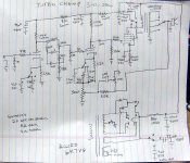
Here is the schematic I am working with:

The fender amplifiers for the build I am attempting switched to a interleaved transformer design for the circuit I am attempting to adapt it to. As such, I am trying to provide this a more robust OPT.
This is what I would like to adapt it to, sans the “normal input”:

Of course the current draw is increased with the extra tubes but the concept remains the same; the output tubes are being replaced by a dual triode 12BH7.
Here is the schematic I am working with:
The fender amplifiers for the build I am attempting switched to a interleaved transformer design for the circuit I am attempting to adapt it to. As such, I am trying to provide this a more robust OPT.
This is what I would like to adapt it to, sans the “normal input”:
Of course the current draw is increased with the extra tubes but the concept remains the same; the output tubes are being replaced by a dual triode 12BH7.
Last edited:
4.5 watts per side is too hot. You need to run the idle current a bit lower. I would aim for 3 watts or less. The typical operation data uses 2.875 watts.If you operate the 12BH7 at 300V x 0.015A (15mA), the plate is dissipating 4.5W. Ouch!
If this is a push pull amplifier, with 300V B+, and one plate goes to ground (0 Volts), the other plate will go to + 600V (if it has an infinite load impedance).
But that is not likely.
Remember, this is a guitar amp. Somewhere, sometime some dummy like me will plug a pedal board into this thing, set the controls for the heart of the sun and cut loose driving those output well past clipping. I have seen peaks of over 2500 volts in a working guitar amp that ran 6L6GC's on 430 volts of B+ when playing notes that were around the speaker's resonant frequency. The 12BH7A is however rated for such nonsense. There is a peak positive plate voltage spec of 1500 volts to accommodate the retrace pulse seen in TV vertical sweep operation. Build the amp with whatever OPT you like, play with it, then set the idle current for a point that gives you the sound you like and keeps the plate dissipation down under 3 watts per side. Use a ceramic socket to withstand the high plate voltages seen in overdriven use.
Several of my old small guitar amp builds used the Hammond 125 series OPT's with a switch to connect the speaker to every available tap on the OPT. You never know what someone will connect to it, and often a deliberate mismatch can create a unique sound. Here is the schematic for a SE amp. I built about 10 of these over a several year period from junk box parts. No two were alike, and some even used car audio speakers obtained cheap when a local K-Mart closed down. Most used power transformers salvaged from dead HP audio signal generators resulting in a B+ under 400 volts.
Attachments
Are you after the Fender Vibrosonic sound also? Then please note the main difference in your schematics: You're driving your tone stack from a low impedance cathode follower, same as Jim Marshall does. Although this also may sound fine (I'm sure it does!), it surely won't sound like the same tone stack driven from a high impedance 12AX7 plate.The fender amplifiers for the build I am attempting
Best regards!
Thanks for looking out.Are you after the Fender Vibrosonic sound also? Then please note the main difference in your schematics: You're driving your tone stack from a low impedance cathode follower, same as Jim Marshall does. Although this also may sound fine (I'm sure it does!), it surely won't sound like the same tone stack driven from a high impedance 12AX7 plate.
Best regards!
The impetus for the project was actually the Revibe (reverb + harmonic tremolo unit). I already have a reverb tank so I was just going to build a standalone Harmonic Tremolo unit. Then I realized I was only two subminiature tubes (LTP phase inverter and push pull output) away from a micro amplifier. I’m going to follow the Fender 6Gxx-A schematic; the Bassman micro schematic is to illustrate the phase inverter and output tube circuit. To be honest I don’t know if I’ve heard a Vibrasonic. I have heard a Jazzmaster driving a 6G14 Showman through a JBL D131 in a tone ring cabinet and love the sound. For a micro amplifier head build the 6G14 Showman and 6G13 Vibrasonic would be identical.
I found this chart regarding various subminiature “power tubes” in the micro guitar amplifier schematic posted above:

Interesting that the dissipation on some of the tubes is higher than is recommended on the datasheets for said tubes. Is this typical for guitar amps?
Interesting that the dissipation on some of the tubes is higher than is recommended on the datasheets for said tubes. Is this typical for guitar amps?
So my “16 ohm” JBL D130 arrived yesterday. I immediately open the package to test the driver w/ DATS. I’m sitting there scratching my head wondering why this 16 ohm driver has an Re of 6.4 ohms. The cone is original - it was not reconed. Then, after a little googling, I find this posted on another forum (from the horse’s mouth, Harvey Gerst):
Pretty funnySimple answer:
Back then, we lied.
Even though they're marked as 16 Ohms, they were all really 8 Ohm speakers. The DC resistance should be around 70% of the nominal rated impedance, so an 8 Ohm speaker should read about 6 Ohms (or so) DC. Ignore the 16 Ohm decal; it was really an 8 Ohm speaker. It hasn't been reconed.
Re is only part of the impedance. Acoustic load, mass, and treble inductance all add some in the low-point and more outside the dip. For the usual 1/2%-1% efficient speakers, this comes to a few a part-ohms, which makes 6 Re a nominal 8. The D130 is way efficient, 8% IIRC, so the mass and acoustic loading add several ohms. It may never really come down to 8 ohms in the audio band, and spend so much time over 12 Ohms that you could round to "16 nominal". And being so efficient, it is very rare for the amplifier to strain. Even salsa in the park, or oldies in the 3,000 seat movie house.16 ohm driver has an Re of 6.4 ohms
That’s great because I ordered a 10W 12K:4 transformer from Edcor’s guitar amplifier series (GXPP10-12K). It’s rated 40~18K Hz., <1dBu. The Hammond 125x series is only rated to +/- 1dB 100-15K.
- Home
- Amplifiers
- Tubes / Valves
- Speaker mismatch and how it effects the output transformer