Hello,
The speaker-level inputs to my Cambridge Soundworks Newton P200 (active) subwoofer consist of a 470 ohm resistor across the terminals, followed by other circuitry. I was expecting a simple voltage divider using higher resistances so that 1/4 watt resistors could be used. I'm assuming there is a good reason for the lower impedance to justify the use of the higher-wattage resistors I see on the board. Is there a standard reason why the designers made that choice?
For some background, I'm asking is because the amp inside the subwoofer has died. Instead of trying to fix it I am simply replacing the amp with a cheap tda3116 board (powered by an old laptop supply) and am re-using connectors and such as much as possible to minimize cost. It is this board:
https://www.amazon.com/AOSHIKE-Subwoofer-Amplifier-amplifier-Accessories/dp/B01N5DGK37/
The subwoofer is in a room where we only listen to music at low volumes so I'm guessing even a 20W amp is good enough to replace the 200W that failed. The sub is fed via in-wall speaker-cables from a receiver in the next room - hence the speaker-level input question. The satellite speakers run full-range (they go down to about 80 or 100 Hz) so I don't use the sub to filter the signals to the satellites. If I yank out the 470 Ohm resistors then I can more easily reuse part of the input board to place a simple voltage-divider before the new amplifier. I used such a divider on a breadboard when testing the tda3116 amp in my setup and it seemed to work well with my receiver.
Thanks,
jason
Last edited:
I don't see why you can't use a simple voltage divider, particularly if you've already confirmed it works satisfactorily in your test.
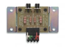
Commercially available speaker to line level adaptors do precisely that (see attachment).
Commercially available speaker to line level adaptors do precisely that (see attachment).
Attachments
Last edited: