I'm planning on building an spdif input selector board with a digital mux for two BNC(Coax spdif) and Two toslink inputs. My problem here is the the Coax is CMOS level and the toslink is TTL.
My Buffalo III-SE can take both CMOS and TTL straight into the board, but i don't want to use relay switching.
So digital signalling is not what i'm best at, but as far as i know the only difference between these two is the voltage level when 1 is a 1 and 0 is a 0.
At least that is how i see it when looking at this page Logic Voltage Thresholds for TTL, CMOS, LVCMOS, and GTLP IC families
So, have i understand it right that it would work fine to switch both these signals (with CMOS output) with a TTL/CMOS mux like 74HCT153.
If i have understand the above right the TTL/CMOS input would take anything above 1.5v (up to 4.7v) as a 1, and anything below 0.8v as a 0. So the only difference for CMOS signal would be that the low limit comes at 0.8v instead of 1.3v which shouldn't be much of a trouble?
If this is right - then i just wonder would i need a "dual" multiplexer really, or would a single be fine? (thinking if it was a analog switch ic like HEF4052B i would need dual multiplexer to switch both digital signal and ground) thinking all inputs go to 1I0 + gnd, 1I1 + gnd, rather than 1I0 + 2I0, 1I1 + 2I1 and so on. And outputs the same Y1 + gnd, rather than Y1 + Y2.
If the last part is right i guess 74HCT151 would be "better" since it can enable up to 8 inputs.
EDIT: Damn, SPDIF-Coax levels are only 0.5v and not CMOS. Don't know where i got that from. Then the idea is screwed i guess, and a convertion to ttl is needed before?
Any help would be appreciated!
Last edited:
Befor you switching the spdif signal, you have to convert it to digital level.
After conversion , I use a single UHS buffer with Three-State Output (NC7SZ125) to built a mux for spdif and I2S signals.
After conversion , I use a single UHS buffer with Three-State Output (NC7SZ125) to built a mux for spdif and I2S signals.
Do you have any circuit to convert coax to TTL, and what IC to use?
Since i won't need I2S switching (there is a separate i2s input on the dac) then a simple 74HCT151 would work as fine?
Since i won't need I2S switching (there is a separate i2s input on the dac) then a simple 74HCT151 would work as fine?
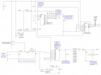
I designed but did not build a very similar project. I will attach the schematic. Maybe you will find some inspiration. Feel free to contact me if you have questions.
Here are some links about different parts of the circuit. You will want to read the epanorama web page on SPDIF interfacing.
hardware:svnimages:irspdif_single.sch.png [Projects]
epanorama.net/S/PDIF Interface
www.netstuff.org (see SPDIF Master)
Pushbutton Relay Selector Circuit Diagram
Essentially it takes SPDIF input, converts to TTL levels, then uses a TTL MUX that is controlled by a neat little pushbutton activated selector via a BCD interface. The output of the MUX is converted back to SPDIF. This was going to be used as a digital preamp input selector, and I just got stalled out on the project. If anyone wants to help me and contribute something, I'd love to actually build this.
This concept has been used by several people who built successful projects, so I know it works up to 96kHz.
-Charlie
Attachments
Last edited:
http://www.twistedpearaudio.com/digital/torx.aspx
Use that circuit for both optical inputs together with 2 SPDIF inputs to the Wolfson WM8805. Or is that too simple ? 50 ps jitter and up to 8 inputs....Why would you build your own jittery mux when a device already exists that muxes quite well and costs only a few Euro ? Or it must be that you like to reinvent the wheel 😉
Use that circuit for both optical inputs together with 2 SPDIF inputs to the Wolfson WM8805. Or is that too simple ? 50 ps jitter and up to 8 inputs....Why would you build your own jittery mux when a device already exists that muxes quite well and costs only a few Euro ? Or it must be that you like to reinvent the wheel 😉
Last edited:
http://www.twistedpearaudio.com/digital/torx.aspx
Use that circuit for both optical inputs together with 2 SPDIF inputs to the Wolfson WM8805. Or is that too simple ? 50 ps jitter and up to 8 inputs....Why would you build your own jittery mux when a device already exists that muxes quite well and costs only a few Euro ? Or it must be that you like to reinvent the wheel 😉
That Wolfson chip looks great. Do you know of something like it that includes a sample rate converter before the transmitter?
By the way, your link generates an error. Can you check the source URL?
That Wolfson chip is great, one of the better ones on the market. The Twisted Pear site seems down...but there are enough other schematics involving TORX receivers around. You know coax SPDIF is better technically do you ?
I am sorry but I am very allergic to sample rate convertors so I can not advise you on those (except to not use them).
I am sorry but I am very allergic to sample rate convertors so I can not advise you on those (except to not use them).
Last edited:
TOSLINK Optical Input Module
Use that circuit for both optical inputs together with 2 SPDIF inputs to the Wolfson WM8805. Or is that too simple ? 50 ps jitter and up to 8 inputs....Why would you build your own jittery mux when a device already exists that muxes quite well and costs only a few Euro ? Or it must be that you like to reinvent the wheel 😉
I already have two torx-units for optical. But i was thinking WM8805 would need quite big board - since it would need regulators for XO, Chip itself and so on. But maybe you are right.
I'll have to look into it. I2s would actually probably be even better as input - because then you can reclock the signal and run the dac sync.
By the way, the WM8805 doesn't work to change inputs with Hardware mode as far as i can see, so there goes that alternative also :-(
Since i use AMB LCDuino to change input/volume and i have a pretty stuffed case, what i need is a small PCB and possiblity of 2-bit input selector for the SPDIF, otherwise the 8805 looks perfect since it even does have i2s output (even better for me).
Since i use AMB LCDuino to change input/volume and i have a pretty stuffed case, what i need is a small PCB and possiblity of 2-bit input selector for the SPDIF, otherwise the 8805 looks perfect since it even does have i2s output (even better for me).
- Status
- Not open for further replies.
- Home
- Source & Line
- Digital Source
- SPDIF input switching....