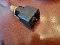
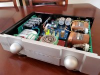
Hi folks, I've got an audio mirror tubadour dac and do to quarentine boredom decided I wanted to replace all the rca connectors with wbt-ag units. Unfortunately I somehow broke the spdif input.
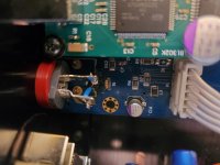
It had one of those "on board" connectors that come on prefab circuit boards and I cut it off and replaced it with my wbt and some 75ohm wire. Unfortunately I couldn't get a signal after that (including by putting the original connector back in). I did have to manhandle it quite a bit to get it out of there, but there's not really anything going on in that corner of the board.
Anyway, after replacing I had continuity from rca inner sleeve through the 75ohm input resistor (and measured a nice 75ohms) and from rca ground to why inside grounding connector.
I've included an image in case anyone has some troubleshooting tips. I'm out of my comfort zone in digital unfortunately...
My I2S input still works, so whatever I did is localized to spdif (I also replaced all signal wire while I was in there).
Thanks for any input. Really don't want to part with the music machine to get manufacturer repair...
Attachments
I should also note that I'm an idiot and didn't do appropriate testing after first install and had a piece of shield from my 75ohm cable touching the signal wire, so it was shorted on the first plug in.
One final note as I mull over the situation. The hole for the SPDIF ground/shield is clogged and no amount of heating and vacuum pumping or resoldering wire (or pushing heated solid core wire through the hole) can get it open. When I fully had the board out, I was able to clear it with a lot of effort, but as soon as I tried to rework it after failing on my first attempt it remained clogged.
Afterwards I just soldered to the pad and checked for continuity with other internal grounding. I assumed that meant I was fine.
Afterwards I just soldered to the pad and checked for continuity with other internal grounding. I assumed that meant I was fine.
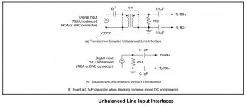
The 75-ohm resistor will go to ground, as it is for terminating the coax transmission line. Usually there is also a capacitor connected to the SPDIF input. The cap couples the SPDIF signal to the rest of the SPDIF receiver electronics.
The circuit might look like one of the two shown below. Some SPDIF receivers have differential inputs (as shown in the diagram), and some are single-ended (with only a non-inverting input, RX+).
The circuit might look like one of the two shown below. Some SPDIF receivers have differential inputs (as shown in the diagram), and some are single-ended (with only a non-inverting input, RX+).