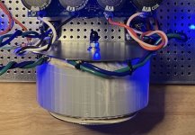
I used all thread rod to stack the filter caps on top of the transformers for my dual mono F6 build.


I've been thinking about grounds and current loops for a while now, so I'll clarify my thoughts on this, I would suggest trying to wire any high current 'loop' (send+return, i.e. source/drain or emitter/collector) as a twisted pair so the current stays in that one path, then the 3rd wire (gate or base) can be thinner, and perhaps shielded from one end.Yep, transistors.
So yes, shorter is better, but to avoid building mini inductors/magnetic field generators (that then also play the music) - twisted wires on the high current side is probably wise if possible/long.
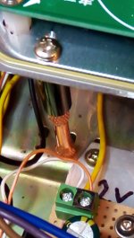
Thanks for this reference, I looked - please excuse my crop of your photo - and have decided to copy your transformer mounting idea here! The big steel L plate, shielding it from the amplifier side, and the orientation saves space, so your method completely solves my (newly discovered LOL) hassles with my horizontal transformer 'partial turn magnetic interference' generator, and shields the LH channel of the power amp too which is close to that side.with my f6
So today I'll be banging out an L bracket from a nice thick piece of galvanised steel I have, to reconfigure that bit 🙂
Attachments
The reason I asked about distance between boards and transistors is because I’ve have the parts for this chassis. Here is a crude drawing of the chassis. It will be as long as necessary to fit all the heat sinks and about 10 inches wide.
It will be made from aluminum and maybe anodized or polished.

It will be made from aluminum and maybe anodized or polished.