Single-ended (RCA) input (AUX2)
An externally hosted image should be here but it was not working when we last tested it.
Ummh...
I'm not sure I understand the "XLR Pin1" errors you're referring to.
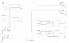
Here's my intention (and hopefully the drawings reflect that):
1. Pin1 of inputs are tied together.
2. Pin1 of outputs are tied together.
3. Pin1 of outputs are ALWAYS tied to "Chassis Gnd".
4. Pin1 of inputs are conditionally tied to Pin1 of outputs.
That is, the DPDT-CO "LIFT" switch provides the option to:
(a) leave Pin1 of inputs floating (thus the name "LIFT")
(b) tie Pin1 of inputs directly to Pin1 of outputs (Hard Gnd)
(c) tie Pin1 of inputs via 1.5 resistor to Pin1 of outputs (Soft Gnd)
5. Pin1 of outputs is connected to Pin3 of outputs for single-ended ("RCA") output mode, as selected by the DPDT XLR/RCA switch.
6. And, lastly, for the single-ended (RCA) input case (AUX2 in the revised schematic), RCA common/ground of that input is connected to Pin1 of other input XLR's, and potentially to Pin1 of outputs (and "Chassis Gnd"), via the the LIFT switch.
Can you please explain what I missed?
Thanks.
Kevin,When you re-drew the schematics, why didn't you correct the XLR pin #1 errors?
I'm not sure I understand the "XLR Pin1" errors you're referring to.
Here's my intention (and hopefully the drawings reflect that):
1. Pin1 of inputs are tied together.
2. Pin1 of outputs are tied together.
3. Pin1 of outputs are ALWAYS tied to "Chassis Gnd".
4. Pin1 of inputs are conditionally tied to Pin1 of outputs.
That is, the DPDT-CO "LIFT" switch provides the option to:
(a) leave Pin1 of inputs floating (thus the name "LIFT")
(b) tie Pin1 of inputs directly to Pin1 of outputs (Hard Gnd)
(c) tie Pin1 of inputs via 1.5 resistor to Pin1 of outputs (Soft Gnd)
5. Pin1 of outputs is connected to Pin3 of outputs for single-ended ("RCA") output mode, as selected by the DPDT XLR/RCA switch.
6. And, lastly, for the single-ended (RCA) input case (AUX2 in the revised schematic), RCA common/ground of that input is connected to Pin1 of other input XLR's, and potentially to Pin1 of outputs (and "Chassis Gnd"), via the the LIFT switch.
Can you please explain what I missed?
Thanks.
Last edited:
XLR pins #1 should:
a] Be connected directly to the chassis as near as practicable to the connector.
b] Should NOT be connected to other connectors or other components (switches & resistors).
c] Should NOT be part of the audio circuit.
a] Be connected directly to the chassis as near as practicable to the connector.
b] Should NOT be connected to other connectors or other components (switches & resistors).
c] Should NOT be part of the audio circuit.
What I would do is:
a] Eliminate all the lift switches, all the 1.5K resistors and all the RCA phono connectors.
b] Correctly wire the XLR pins #1.
c] Modify balanced interconnects to gain the other features.
That is if you need an unbalanced input or output, put the correct connector on the far end of a balanced interconnect.
If you really want to dis-connect a balanced shield do it inside the cable connector.
To the "XLR Pin1 police"...
BTW, I've made all the changes (but kept AUX2 with XLR's for now), and it all sounds great!
Thanks for the feedback.
OK, as revised, I did tie all pin1 inputs together, and removed LIFT switches, except for one (which does allow for tying pin1 of the outputs to the inputs; while providing the option to float the inputs... just my preference!).What I would do is:
a] Eliminate all the lift switches, all the 1.5K resistors and all the RCA phono connectors.
b] Correctly wire the XLR pins #1.
c] Modify balanced interconnects to gain the other features.
Ummh... I do need unbalanced/RCA outputs, so if I used a converter cable (as you suggest), what would that cable do?: (1) tie XLR-pin2 to RCA-signal (2) tie XLR-pin3 & pin1 to RCA-common... which should be effectively what I've accomplished by having RCA outputs, coupled with the RCA/XLR switch (so, I chose to leave that as-is).That is if you need an unbalanced input or output, put the correct connector on the far end of a balanced interconnect.
If you really want to dis-connect a balanced shield do it inside the cable connector.
BTW, I've made all the changes (but kept AUX2 with XLR's for now), and it all sounds great!
Thanks for the feedback.
An externally hosted image should be here but it was not working when we last tested it.
Last edited:
You might read some of Tony Waldron's papers on interconnects and EMI/RFI interference.
Tony Waldron's EMC ranting and ravings
Tony Waldron's EMC ranting and ravings
XLR pins #1 should:
a] Be connected directly to the chassis as near as practicable to the connector.
b] Should NOT be connected to other connectors or other components (switches & resistors).
c] Should NOT be part of the audio circuit.
Jensen Transformers, at least, don't agree:
http://www.jensen-transformers.com/as/as035.pdf
Note the ground lift switch.
As shown in the updated schematic, I've added:
1) Input: Gain selector switch (0db/+6dB)
2) Output: RCA connectors & associated mode switch
3) Soft/Hard Grounding options (LIFT)
An externally hosted image should be here but it was not working when we last tested it.
Did you run any tests on this device? I'd be curious as to bandwidth, phase shift, distortion, noise, etc.
No, I did not run any tests.Did you run any tests on this device? I'd be curious as to bandwidth, phase shift, distortion, noise, etc.
Since it is not an active device, I suppose the specs from the transformer manufacturer's (Sowter) should be applicable.
Jensen Transformers, at least, don't agree:
http://www.jensen-transformers.com/as/as035.pdf
Note the ground lift switch.
I must admit not being an expert on ground issues, and optimal ground wiring configurations (especially with respect to XLR input and output connectors, and combining that with single-ended RCA connections as well).
So if you, or anyone else on this thread, would like to propose an alternate wiring diagram, please do so (a picture of the updated diagram would be great)... I would certainly appreciate your contribution.
Jensen Transformers, at least, don't agree:
http://www.jensen-transformers.com/as/as035.pdf
Note the ground lift switch.
Note the date on that paper. (9-18-1995)
It pre-dates much of the work on the pin #1 problem.
In any case it shows an input connector using a hybrid circuit to the chassis.
Last edited:
Note the date on that paper. (9-18-1995)
It pre-dates much of the work on the pin #1 problem.
In any case it shows an input connector using a hybrid circuit to the chassis.
Then maybe you should go lecture them about it if it's that important to you. Let us know what they say.
I must admit not being an expert on ground issues, and optimal ground wiring configurations (especially with respect to XLR input and output connectors, and combining that with single-ended RCA connections as well).
So if you, or anyone else on this thread, would like to propose an alternate wiring diagram, please do so (a picture of the updated diagram would be great)... I would certainly appreciate your contribution.
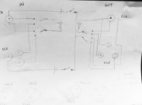
Generally, you should connect all XLR pin #1's to the chassis at the connector unless you need the feature of a ground lift. For the RCA connectors, they should not be connected to chassis ground at all. They get connected to the transformer in the same way as pins #2 and #3 of the XLR connectors.
It is best by far to use a very short wire directly from the XLR #1 pin to the chassis. An excess wire inside the chassis just acts as a noise antenna. Any hybrid or open shield connect at the receive end should be done in the cable connector.
This quick drawing is how I would do it.
Note: The unbalanced shield connections may not all be necessary.
This quick drawing is how I would do it.
Note: The unbalanced shield connections may not all be necessary.
Attachments
Ouch...you may run into ground-loops/hum-problems by connecting all pin-1/rca-shield to chassi. I would as a simple sollution use a 4,7-10 ohm resistor between all pin-1 and chassi(ground), just to "break" any loops. Same for RCA-shield. Have worked for me...
Arne K
Arne K
Ouch...you may run into ground-loops/hum-problems by connecting all pin-1/rca-shield to chassi. I would as a simple sollution use a 4,7-10 ohm resistor between all pin-1 and chassi(ground), just to "break" any loops. Same for RCA-shield. Have worked for me...
Arne K
No, it's only a potential problem tying the RCA shield to chassis since balanced audio has zero current in the shield whereas single ended does have ground current. It's normal practice I believe to insulate the RCA jack from the chassis. Since there's a transformer in here, both the RCA hot and ground can be directly connected to the transformer in the same way that pins #2 and 3# from the XLR are connected, without touching any ground or chassis. Of course, the RCA ground is connected to a ground in the upstream equipment, and the RCA ground is also connected to a ground in the downstream equipment. Transformers are very useful for breaking ground circuits and preventing hum from ground loops.
OK, how about this?
1) Got rid of the single-ended RCA inputs, so that simplifies things.
2) Tied pin 1 of all XLR's to "chassis" ground (individual wires, in "star", and as short as possible)
Thanks for the feedback.
1) Got rid of the single-ended RCA inputs, so that simplifies things.
2) Tied pin 1 of all XLR's to "chassis" ground (individual wires, in "star", and as short as possible)
Thanks for the feedback.
An externally hosted image should be here but it was not working when we last tested it.
Last edited:
Hi everyone,
I have a nice russian NOS 23 step rotary switch and was looking at building a stepped attenuator.
I was looking at TVCs and came across the 9335 from Sowter. Not that expensive as others, but was keen to see if anyone had any references about it?
SOWTER ATTENUATOR TRANSFORMERS TVC VOLUME CONTROL
Thanks
Ale
- Status
- Not open for further replies.
- Home
- Source & Line
- Analog Line Level
- Sowter-based TVC