The 3uF and a 12uF are in series with the tweeter (the 3 is paralleled with a resistor)
If there is NOT a capacitor (EDIT: an additional resistor will just be another potential thermal failure point) in series with the CR parallel contour, or for that matter, ANY component between the CR and the input terminals, this is a VERY BAD idea. The resistor will be in series with the shunt coil between the 2 caps, and placed directly across the amplifier terminals. This is seen as a close-to-short situ, or a possible fire-starting problem when that resistor heats up with seeing the entire bandwidth due to no highpass fore or aft.
The 40uF is in series with the woofer (paralleled with an inductor and resistor).
If this is a 2-way, then I would opt for a poly on the 40uF as it will influence the midrange performance.
The 8.2uf, a 12uf and 16uf all go from the woofer signal to ground.
These I would also favor poly, but nothing more than a Solen FC is really required.
I highly recommend you look at the tweeter highpass and evaluate that issue.
Best regards,
Wolf
Last edited:
thanks for the info. My brain is running a bit slow this morning, but if I'm following correctly, that means as long as there is a capacitor that isn't bypassed with a resistor in series with the tweeter it is okay. Because if the bypassed capacitor fails it puts the full frequency current on the resistor and to the tweeter, correct?
It really has nothing to do with the tweeter in this case. It has to do with the amplifier seeing a resistance without bandwidth limitations, and heating the resistors up. It's also not about a cap failing, but about the setup being a thermal issue and starting a fire.
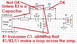
In the below example, the loop of R3/R1/L1 loops resistance directly across the amplifier terminals without the aid of a highpass capacitor, because the R1 bypasses it in the circuit. Basically, if you have nothing but resistance and inductance across an amplifier, the resistances will get pretty warm unless they are either substantial power handling and heatsinked, or there is a capacitor in the line. If R3 were a capacitor, then this would all be fine because the resistors become bandwidth limited. Since it is not a cap, or were R3 omitted completely (same for both situations), this situation will allow R1 to pass a lot of current into the bass range of the speaker system, and therefore dissipate a lot of heat to the point of being possibly overdriven and fried. IE- fire!
If R1 were missing, this circuit would be fine, even with or without R3. This is because there is no straight path across the amp without a cap in the line when R1 is not present.
To top it off, even if you have a smoke-proof 100W resistor on a massive heatsink, R1 is still not a very good idea. This is because it defeats the highpass on the tweeter. If R1 and R2 were infinite resistance, the tweeter would be safer than if the resistors are present. They defeat the highpass capacitors' usage more and more the lower the value of resistance chosen.
R2 is perfectly fine to use were R1 not there, as it's not across the amplifier that way.
There is nothing novel or superior about using R1, especially due to the risks of both personal property and the tweeter under moderate output.
Friends do not let friends use R1 as in this instance.
Hope this helps,
Wolf
Attachments
As Wolf said, in that schematic the amp is playing a resistance as there is no cap in the chain between plus and ground on the amp. It’s a short. You might think well there is no cap in the woofers path but that is different because the power goes into moving the woofer rather than wasted as heat. If no sound is being made the power goes to heat.