Hello everyone,
I'm working on a SoundStream LW4.620 that has DC on the output without a signal and a square wave with a signal.
Everything checks out both in and out of the circuit.
Someone has worked on it before.
So far, I’ve found some disconnected jumpers and a failed diode. I’ve replaced all of them, but the issue persists.
All four channels have the same fault.
Does anybody know or have experience with this issue?
Any help would be greatly appreciated. 🙏
Signal on the base of the output transistors before clipping⬇️
This amplifier is identified as a Class AB output stage from a brief internet search. That means the half-sine wave signal measured on the base of the transistor is correct for the lower (negative) half of the amplifier (probably PNP).
The first board picture also shows two groups of each two transistors missing on the left; probably removed as there's seemingly flux residue. Where are these transistors? Where did they go? Did you remove them?
- Does the upper (positive) half have the other half of the sine wave present there?
- Is the DC offset present on the square wave output you get when a signal is applied?
- What signal do you apply that results in a square wave output? (sine?)
- Is the DC offset on either without or with signal a positive or negative voltage with respect to ground?
The first board picture also shows two groups of each two transistors missing on the left; probably removed as there's seemingly flux residue. Where are these transistors? Where did they go? Did you remove them?

- Does the upper (positive) half have the other half of the sine wave present there?
- No, just the negetive half which is starting from positive rail and not ground
- Is the DC offset present on the square wave output you get when a signal is applied?
- The outputs are always at positive 24v (positive rail) without any signal applied to the input
- What signal do you apply that results in a square wave output? (sine?)
- I'm applying 1KHz Sinewave and after a certain amount of gain it gradually starts to build the negetive half from positive rail on the output until it goes into full squarewave( upper part of the square wave is the positive rail)
- Is the DC offset on either without or with signal a positive or negative voltage with respect to ground?
- The DC is always present and it's 24v, the positive rail voltage.
I replaced this diode which is connected to the positive rail and those 3 jumpers which are connected to the ground⬇️
I've removed the power transistors (TIP35/36c) to prevent further damage while trying to diagnose the problem because they were getting hot (due to cross conductions)The first board picture also shows two groups of each two transistors missing on the left; probably removed as there's seemingly flux residue. Where are these transistors? Where did they go? Did you remove them?
Is the amp producing both positive and negative rail and ±15v?
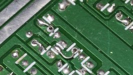
These amplifiers with this idiotic version of a double-sided board is VERY unreliable unless you reconfigure all solder connections for any lead that has solder on both sides of the board. This includes the leads where there is a pad on both sides of the board but no trace leading away from one of the traces. The best looking repairs will be where you solder the top side and then solder the bottom side of the lead to an adjacent point on the bottom pad. Attached is one example. You must do this for every one of theses types of connections or it will fail again. Simply resoldering them will only be a temporary repair.
When you receive an amp like this, you should either punt or factor in the additional labor required to do this the right way.
Attachments
Yes, it's producing the +-15 v and +-24v rails.Is the amp producing both positive and negative rail and ±15v?
I will do as you suggested for all the jumpers and other similarly connected parts.These amplifiers with this idiotic version of a double-sided board is VERY unreliable unless you reconfigure all solder connections for any lead that has solder on both sides of the board. This includes the leads where there is a pad on both sides of the board but no trace leading away from one of the traces. The best looking repairs will be where you solder the top side and then solder the bottom side of the lead to an adjacent point on the bottom pad. Attached is one example. You must do this for every one of theses types of connections or it will fail again. Simply resoldering them will only be a temporary repair.
Thanks 🙏
I removed them to prevent further damage while diagnosing the driver circuit, they were TIP35/36C pairsWEre the TIP outputs the original part numbers used?
But are they what the original circuit calls for?
I'd suggest measuring continuity from your output terminal + to the main voltage rail +. With the amp fully disconnected of course.
What does the other end of the diode connect to, and in what kind of way were the jumpers bad? Did they burn through, melt, explode? The failure mode would tell us a lot about what could be wrong.I replaced this diode which is connected to the positive rail and those 3 jumpers which are connected to the ground⬇️
I'd suggest measuring continuity from your output terminal + to the main voltage rail +. With the amp fully disconnected of course.
I will check and keep you updated here.What does the other end of the diode connect to, and in what kind of way were the jumpers bad? Did they burn through, melt, explode? The failure mode would tell us a lot about what could be wrong.
I'd suggest measuring continuity from your output terminal + to the main voltage rail +. With the amp fully disconnected of course.
The jumpers were replaced by someone before, but they weren't making a good connection with the solder. So, I replaced them, but there were no signs of overheating or anything similar.
The 24V DC on the output is a result of the output transistor fully turning ON. There isn't a direct connection between the transistors and the positive rail.
Is that something you checked and verified to be the case? If it were the result of the transistor being turned on, you'd expect about 0.2-0.4v drop (at the very least) compared to the input voltage. Do you see that voltage drop? That's the saturation voltage drop on BJT'sThere isn't a direct connection between the transistors and the positive rail.
I asked about the output transistors because it's rare to have TIP transistors.
In these single sets per channel cheap amps? It's very common. There's a common design out there that uses TIP35C & TIP36C transistors as its output transistors, just one pair. There's four pairs on this board and it's a four channel amp. Expect about 60-80 W with proper power supply.
Now if you go and look at what the amps had originally, they do indeed use TIP35C & TIP36C. In fact, they use obvious fakes with fake STmicro labeling and markings. It's beyond obvious.
It's not surprising, because this is a very cheap bottom barrel amplifier.
Update:With no outputs in the circuit, do you still have 24v on the bridging speaker terminals?
I asked about the output transistors because it's rare to have TIP transistors. They rarely use TIP types.
I followed your suggestions for all the jumpers and other components. The amplifier is now working properly, and the issue has been resolved.
Thanks, Perry 🙏
I can't understand why they still do this. It's a known problem. It's a bit like the brown fixative that turns both conductive and corrosive. Some manufacturers still use it.
- Home
- General Interest
- Car Audio
- SounStream LW4.620 DC on output