Remove the driver transistors. Does that allow the 494 to produce clean output?
Check the drivers carefully while they're out of the circuit.
Check the drivers carefully while they're out of the circuit.
I replaced the 494 with a new one and now i have a perfect squarewave on pins 9 and 10..
I will put the drivers back in and 4 fets and see what i come up with
I will put the drivers back in and 4 fets and see what i come up with
Ok that problem is solved..
Next problem i have is my kids took off with the rectifiers and dont know where they went..
Any idea what rectifiers this amp uses??
Next problem i have is my kids took off with the rectifiers and dont know where they went..
Any idea what rectifiers this amp uses??
Your children should not be anywhere near the area where you repair amplifiers. Lead is toxic to children and can cause brain damage or developmental problems. Simply touching the components puts them at risk.
No clue on the rectifiers.
Seriously... keep the children away from the work area.
https://www.google.com/search?hl=&q..._enUS452US452&ie=UTF-8&aq=0&oq=lead+toxicity+
No clue on the rectifiers.
Seriously... keep the children away from the work area.
https://www.google.com/search?hl=&q..._enUS452US452&ie=UTF-8&aq=0&oq=lead+toxicity+
Thanks for the Info..
I will keep the away from now on..
I found out what rectifiers it uses ..
1 Supply is working fine and produces audio..
Other supply has problems still the fets heat up within 2 secs so im gonna check the outputs in that supply
I will keep the away from now on..
I found out what rectifiers it uses ..
1 Supply is working fine and produces audio..
Other supply has problems still the fets heat up within 2 secs so im gonna check the outputs in that supply
well back to the power supply section Still has problems..
The amp has 4 banks of fets 2 per supply..
All drivers check good.. But the fet in 1 bank blows within 2 secs of powering up..
I checked the gate resistors all check fine..
Any ideas?
The amp has 4 banks of fets 2 per supply..
All drivers check good.. But the fet in 1 bank blows within 2 secs of powering up..
I checked the gate resistors all check fine..
Any ideas?
I think i found the problem.. Solder bridge between the legs of 1 driver..
Im gonna replace the gate resistors anyway since they look burnt but measure fine just so it doesnt look like a cheap repair job...
The 22 ohm resistors i put in that i wasent sure of the value 1 supply it worked fine the other supply it got red hot should i try using a 2 watt resistor to see if it works?
Are you sure that it's a gate resistor and not a pulldown resistor?
A lot of amps use 220 ohm pulldown resistors and they're often 1/2w resistors. 22 ohms for the gate resistors shouldn't be causing any problems.
A lot of amps use 220 ohm pulldown resistors and they're often 1/2w resistors. 22 ohms for the gate resistors shouldn't be causing any problems.
The 22 ohm resistors just keep burning up..
the resistor in question 1 side connects to the middle leg of the IRFZ44the other side connects to a winding on the transformer..
There are 220 ohm resistors next to the gate resistors what connect to the 3rd leg of the fet..
So any ideas what i could try since the 22 ohm resistors that connect to the middle leg keep burning up and the fets keep heating up in both supplys?
Is the capacitor connected to the 22 ohm resistor shorted?
Did you check the drive circuit with the 1k resistors before installing the FETs?
Did you check the drive circuit with the 1k resistors before installing the FETs?
Back to having problems with the Drive circuit..
I installed 4 1K resistors again 1 in each bank..
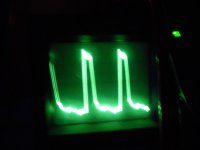
Scope is set to .2us 2 volts div
First pic is the waveform on the gate pad for both supplys..
2ND pic is the waveform on pin 9 of the 494
I installed 4 1K resistors again 1 in each bank..
Scope is set to .2us 2 volts div
First pic is the waveform on the gate pad for both supplys..
2ND pic is the waveform on pin 9 of the 494
Attachments
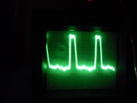
If that's 0.2us, the oscillator frequency is too high. Check the resistor and capacitor on pins 5 and 6 of the 494.
- Status
- Not open for further replies.
- Home
- General Interest
- Car Audio
- Soundstream XTA 880.2