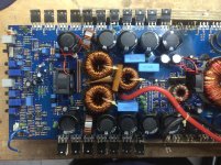
Im working with this amp, all of the driver and power supply mosfets
transistors were shorted, so I cut out all the power supply mosfets legs and
desolder all driver transistors to scope the power supply signal, but there's was no signal at any of the power supply driver board pins.
12 volts are present at the remote pin of the driver board when remote is apply.
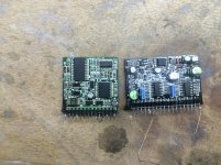
There are two tl494 chips on the driver board. Is it possible that both tl494 are bad?
transistors were shorted, so I cut out all the power supply mosfets legs and
desolder all driver transistors to scope the power supply signal, but there's was no signal at any of the power supply driver board pins.
12 volts are present at the remote pin of the driver board when remote is apply.
There are two tl494 chips on the driver board. Is it possible that both tl494 are bad?

Can some one tell me what are the conditions to test the power supply driver board
Out of the circuit?
Thank you
Out of the circuit?
Thank you
Do you have 12v on pins 8, 11 and 12 and ground on pin 7?
If so, you should have 5v on pin 14. You should see a sawtooth waveform on pin 5 of the 494.
If so, you should have 5v on pin 14. You should see a sawtooth waveform on pin 5 of the 494.
Yes, all voltages and sawtooth waveform at pin number 5 are present, but no signal out of pin 8 and 11of ic tl494.
The output will be on 9 and 10. 8 and 11 are 12v supply pins in this amp. All pin numbers are for the 494.
Both chips are reading the same voltages
Before remote.------After romote
1) 0 v.---------------1) 0v
2)1.5v.---------------2) 5v
3) .2v.---------------3) .68v
4)1.5v---------------4) 5v
5) .18v---------------5) 1.5v
6) .2v----------------6) 3.5
7) 0v----------------7) 0v
8) 13v---------------8) 13v
9) 0v----------------9) 0v
10) 0v--------------10) 0v
11) .8v-------------11) .8v
12) 0v--------------12) 13v
13) 1.2v------------13) 5v
14) 1.5v------------14) 5v
15) 1.5v------------15) 5v
16) 0v--------------16) 0v
Last edited:
Pin 4 is shutting the output of the IC down.
Pins 1 and 7 of US3 should be very near ground. If they are not, post the DC Voltage on all pins of US3.
Pins 1 and 7 of US3 should be very near ground. If they are not, post the DC Voltage on all pins of US3.
Does pin 4 of the driver board have a short or solder bridge to pin 5?
Pin 4 should be near ground but it appears to have voltage on it. If it's not shorted to pin 5, ground it.
Pin 4 should be near ground but it appears to have voltage on it. If it's not shorted to pin 5, ground it.
Pin 4 is not shorted to pin 5, I grounded pin 4 and lost my 12 volts to pin 5.
( R3 burned.)
Replaced R3, and disconnected pin 4 from the driver board, now I have signal, but the relay circuit does not activate, unless I disconnect one leg of D8.
I'm trying to find out where this 12 volts on pin 4 are coming from, but its
very hard to fallow this trace.
Amp is playing audio when test it with the condition mentioned above.
Last edited:
You were asking what to do with the board out of the amp. Is the driver board back in the amp now?
- Status
- Not open for further replies.
- Home
- General Interest
- Car Audio
- Soundstream tarántula 6500