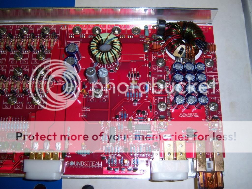
Been trying to figure out whats wrong with a Rubicon 502 board. The board will not power up, none of the leds will light up, no output. The board doesn't have any burnt marks other than some blackish around the bottoms rectifiers(?). Tested each outer legs to:
330k
467k
Any ideas on where to look. Please describe ideas, still in the learning curve.
Pics of the board and attached the schematic.

330k
467k
Any ideas on where to look. Please describe ideas, still in the learning curve.
Pics of the board and attached the schematic.
Attachments
Clamp the transistors tightly to the heatsink and insert a 10 amp fuse in the B+ line.
Power the amp up and post the voltage on all 16 pins of the SG3524.
SG3524
Pin 1:
Pin 2:
Pin 3:
Pin 4:
Pin 5:
Pin 6:
Pin 7:
Pin 8:
Pin 9:
Pin 10:
Pin 11:
Pin 12:
Pin 13:
Pin 14:
Pin 15:
Pin 16:
Power the amp up and post the voltage on all 16 pins of the SG3524.
SG3524
Pin 1:
Pin 2:
Pin 3:
Pin 4:
Pin 5:
Pin 6:
Pin 7:
Pin 8:
Pin 9:
Pin 10:
Pin 11:
Pin 12:
Pin 13:
Pin 14:
Pin 15:
Pin 16:
Here is a little more detailed info on your troubles, just trying to be helpful...🙂
Q68 is a MPSW51A and it supplies the 12 volts to the LM3524 PWM control chip.
Q69 is a MPS8099 and it is the turn on transistor for the amp, thus it gets the 12 turn on through this transistor to the PWM supply.
TS1 and TS2 are temperature switches and they can inhibit turn on if they are dysfunctional...
This info plus what Perry has asked for should get you started on your quest...🙂
NP any help is welcome.
I didn't have much luck in tracing the out the pins. If I'm right then..
Pin 1: 0.00
Pin 2: 2.74
Pin 6: 3.24
Pin 7: 2.21
Pin 10: 0.00
Pin 14: 0.00
Pin 16: 4.92
I did measure each pin with the amp facing in front of you, top pins from left to right:
4.92, 11.35, 0.00, 11.35, 11.35, 0.00, 0.02, 0.18
Bottom pins from left to right:
.002, 2.74, 0.28, 0.00, 0.00, 3.24, 2.22, 0.00
Pin 9 needs to go higher for the IC to produce output. From the input voltages, it appears that something external is pulling it down. Remove and check D18. C57 may be leaking (electrically) which could pull it down.
With D18 out if the circuit, all transistors clamped tightly to the heatsink and a 10 amp fuse in the B+ line, power up the amp. Does it produce rail voltage with D18 out of the circuit?
With D18 out if the circuit, all transistors clamped tightly to the heatsink and a 10 amp fuse in the B+ line, power up the amp. Does it produce rail voltage with D18 out of the circuit?
Pulled D18 and the amp did power up, good sight to see. I checked points TP8 and TP9 with 20.04 / -20.04vdc.
Tested D18 with open and 228v.
Tested D18 with open and 228v.
Replaced C57 and D18 but still will not power up. Took D18 back out and the amp powers up. All three leds stay on red and TP10 and TP11 are showing 16.45.
Any other idea's?
Any other idea's?
Checked all legs of Q38 1-3 were 80 ohms Now the outers of Q51 are 130 ohms but the center and left leg are .996k ohms.
Pulled both, q38 read 80ohms on legs 1 and 3. For Q51 outer legs were OL reversed dmm leads and read the same.
- Home
- General Interest
- Car Audio
- Soundstream Rubicon 502 Repair Problem