I pulled my old Soundstream Reference 644s out of storage to put into my 70 Mach 1 only to find that speaker output on Channel 2 doesn't work. What I find strange is the voltmeter measured 0.06V on Channel 2 but the amps read 0. I measured all four speaker outputs and Channel 1 measured 0.06V, Channel 2 measured 0.06V, Channel 3 measured 0.03V, and Channel 4 measured a little over 0.04V. I pulled the heatsink off to inspect the board and didn't notice anything burnt up or loose. The speaker wires were not getting a bad connection, as I verified the set screws looked fine and was pressing the wires correctly.
Can anyone knowledgeable with these amps walk me through things to check so that I can get it up and running? I noticed member 1moreamp seemed quite knowledgeable on another thread with someone having problems with an old Soundstream board.
Can anyone knowledgeable with these amps walk me through things to check so that I can get it up and running? I noticed member 1moreamp seemed quite knowledgeable on another thread with someone having problems with an old Soundstream board.
The first thing you should check on SS amps is the switches (all switches, top, bottom, side...). With a speaker connected to the dead channel and signal feeding the left and right inputs for that half of the amp, move the switches back and forth repeatedly to see if audio every plays through that channel.
Perry has the correct direction for you to pursue. If its not the switches its likely bad solder joints on the driver board for the dead channel. Very rarely is it anything else causing the issues your describing.
Take a look see and you can try wiggling the driver FEB board for the suspect channel to diagnose bad solder joints. let us know what you find... 😉
Take a look see and you can try wiggling the driver FEB board for the suspect channel to diagnose bad solder joints. let us know what you find... 😉
I did the switches just as Perry suggested, and no sound still came out of Channel 2. I looked at the FEB board real close and all of the soldered joints looked solid. I removed the mainboard from both heatsinks and inspected the backside of the FEB board and it also looked good. I then installed the mainboard back onto the base (which is a pain in the rear getting the LED and switches to line up!), hooked up everything with the top heatsink off, and wiggled the FEB ch2 board and still no sound.
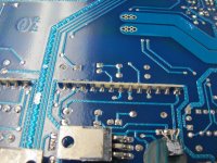
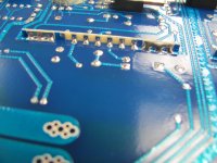
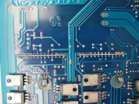
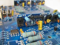
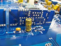
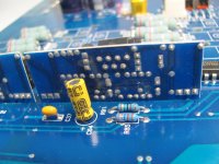
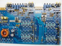
Are there common things that go wrong with the FEB that I can inspect, short of weak solder joints? Can I test certain resistors or items on the FEB to ensure that is the problem? Attached are some pics. I have higher resolution ones but am limited on the size of pics I can attach, so I could email them to anyone should it be needed. I really appreciate the help thus far!!!
Also, something I noticed is if you look at my second pic (back of the FEB board) you will notice pin #4 doesn't have any solder on it. None of the other FEB boards are like that. There doesn't seem to be a track on the main board for the solder to even go to. Just thought I'd point that out. I also noticed none of the FEB boards are labeled on the main board like the resistors and such. I traced the #2 channel to the FEB board I took pictures of, which is the FEB board nearest the center of the mainboard.
Last edited:
Not sure what happened to my pictures. See attached
Attachments
-
 IMG_5084a.jpg251.1 KB · Views: 146
 -
 IMG_5085a.jpg195 KB · Views: 130
 -
 IMG_5086a.jpg282.2 KB · Views: 139
 -
 IMG_5095a.jpg208.6 KB · Views: 130
 -
 IMG_5100a.jpg221.2 KB · Views: 147
 -
 IMG_5101a.jpg193 KB · Views: 87
 -
 IMG_5102a.jpg197.6 KB · Views: 100
 -
 IMG_5091a.jpg263.9 KB · Views: 143
 -
 IMG_5092a.jpg326.7 KB · Views: 107
 -
 IMG_5093a.jpg351.2 KB · Views: 123
Sometimes, and I do stress sometimes the switches do not register even with jogging action. They need to be removed and cleaned or replaced. JandRelectronix on ebay has them. use this link:
jandrelectronix | eBay
I tap on the boards with the plastic end of a screwdriver to get the FEB boards to cut in < just another way of testing them > The problem is so prevalent that I resolder them just to prevent issues later on.
The switches and the bad solder on the FEB boards are the only culprits that come to mind for the symptoms your describing. Please do post pics of any kind or email them to me directly with the address I PM'ed you with....
See post #5. Pics should show now
Are there particular switches that cause this, or can it be any of them? There are 13 of them total. On top there is:
Line Out
CH 1 & 2 Input Level
CH 1 & 2 L Bal/Unbal
CH 1 & 2 R Bal/Unbal
CH 3 & 4 Input Level
CH 3 & 4 L Bal/Unbal
CH 3 & 4 R Bal/Unbal
On the back there is:
CH 1/2 High Pass/Low Pass/Full Range
CH 1/2 Mixed Mono/Stereo/Bridged
CH 3/4 Input/External
CH 3/4 High/Low/FR
CH 3/4 Mono/Stereo/Bridged
For example, I wouldn't think the Line Out or anything regarding CH 3 & 4 would affect the speaker output of CH 2 would it?
Could contact cleaner sprayed into the switch help? Is there a way of testing the switch from the terminals on the back of the board?
Any switches designated for the channel in question can cause this symptom. Yes contact cleaner could possibly help. I have removed the switches and disassembled them cleaned them and reinstalled them before, but replacement is the fastest way to go.
As for the solder joints, they can be difficult to see visually as weather or not they are good. I just touch them up with a soldering iron and possibly add a little more solder to each joint. This amp has preamp boards also < the two little vertical board facing the gain pots. These can fail and Jaime at jandr has them. I would retouch those solder joints also.
The solder reflow is the simplest and fastest to do and then retest. If the problem is still present its most likely the switches or one of those preamp boards. Not much else every fails on these REF series amp. The only other time I saw something similar and it was not the issues listed above it was a bad RCA solder joint on the center pin conductor...
I will be away to day, so please bear with my absents. I will return later tonight....Nice pictures by the way, thanks...
well, solder joints on the boards can be nearly impossible to see, even with a magnifying glass. often times, i need to dig the sharp points of my probes in and run from one end of the solder joint to the other to find that there is a cracked connection..... That being said: in your first 2 pics, i do believe i see several cracked connections, which means you need to Replace the solder joints on all the little upright boards (feb/inversion/etc). i mention to replace the bulk of the solder in the joint over just re-flowing it, due to the fact that it is highly oxidized inside the crack, or it would still be able to make contact. i always throw some nice "silver solder" in there for durability. these little boards have got me more than once, lol. also, it could be either the feb for the channel, or the inversion board, and i cannot stress enough not to power it up without the power supply clamped to the heatsink, even just an idle.
1moreamp, so I guess that narrows it down to 5 possible switches? I never thought to check the preamp boards so I'll check them this evening.
AKHeathen, its tough to get a decent picture of a curved solder joint due to light reflections, but under a magnifying glass I don't see any cracks in the FEB to mainboard joints so it must just be reflections in those pics.That doesn't it isn't separated under the surface as you have mentioned.
Interesting thought about replacing the solder joints instead of touching them up. That would be the proper way to go about it. I don't own a solder pump (thanks Perry for the amplifier repair link!), so I guess its time I get one? Do you use one AKHeathen?
The mainboard was bolted to the heatsink with all factory fasteners prior to testing, but thanks for stressing that!
What are the inversion boards? Are they the little pre-amp boards? I'm an engineer (structural) but not an electrical engineer, so I'm learning a bit about this stuff still. I did stay at a Holiday Inn Express last night though 😉
I use liquid solder flux when I reflow solder joints and I add solder to those that lack proper amounts of solder to be considered adequate IMHO.
GC chemicals makes the liquid solder flux, I use. Its easily removed after it has served it purpose with simple hardware store acetone.
Any residual oxidized solder tends to be picked up by the solder tip, and or is flowed out of the joint well enough to not worry about.
These boards were machine wave soldered and if they ran them thru too fast they always never picked up a proper solder amount to handle the service they see. This is why the problem was so prevalent on these REF models.
Copper traces start to oxidize immediately on contact with air so, a little solder flux tends to clean that up and allow the flowing solder to adhere properly to its surface. If you look closely at these board you will see under the blue solder masking that the traces appear to have been coated with solder before there were sprayed with solder mask coating. This is most likely true because unlike Phoenix Gold and the computer industry where copper traces were gold plated to prevent oxidation and destruction of the copper content Sound Stream decided to solder coat the traces so they would not erode on contact with air and moisture. Copper while doing its job very well tends to be a fairly weak metal and its easily attacked by the elements. You may also notice on say Jl amps they use a brown solder mask coating and PG's TI line and later where the masking was so dark it was very difficult to trace circuitry traces due it opaqueness. They put these coatings on to protect soft copper and the colored coating usually cost way less then nickle hard gold plating, especially with gold hovering around $1800.00 a once nowadays...
But please do as you see fit on your repairs, which ever appeals to your better judgement. After this you should be able to touch up anything that might need it later on, so no biggy once your trained.
Silver solder is fine also but it tends to take a much higher temperature to flow properly, and you risk de-laminating the foil PC board traces, unless your quick about it. 20 something year old copper traces can peal right up off the fiberglass board with too much heat. I use silver solder myself, so I am not saying no, but I am saying be careful if you lack some reasonable time with soldering and the skill set it requires.
I use silver solder on joints that see extreme heat loads since this tends to weaken solder joints with age. Like high wattage drop resistors that see 20 or more volts of voltage drop, such as lower rail regulator drop resistors, ground bonding resistors, Zobel filter networks, etc.. anywhere the resistor is prone to very high heat loads. It always translates back to the solder joint and dull gray oxidized weak solder joints..
Perry recommends Quik chip and its a very good product to aid in desoldering. perhaps it can help you if you run into issues. I keep some here myself along with Indium based low temp solders used for some SMD devices. Check Indium solders price when you get a chance...
PS tapping on the switches can also cause sound to cut in and out. I do this to test them for shock handling also. Road vibration can cause headaches after the service if you don't introduce a little road shock yourself with the plastic handle of a screwdriver, or a rubber ball on a screwdriver tip. < just a old trick I picked up back from my head unit days, tapping the board to find intermittent joints..
Also if you heat up and reflow the switches solder joints on the bottom of the board you might just melt off the hardened junk that tends to coat these switches inside. This may help you to find the culprit without removing the suspected switch from circuit. It seems the open frame switch they used tends to get flux and dirt and grime on its contacts and once some heat hits the contacts it tends to melt loose and allow contact to occur inside the switch, at least intermittently and sometimes.
Again I will be gone most of the day tomorrow also. Sorry but I will be back asap. Perhaps others here can fill in if possible like they have..😉
More than one way to skin a cat. Since I don't own a solder pump, I will look into this liquid solder flux. When you mention reflowing the solder, it is essentially just heating up the existing solder with a heat gun (or solder gun, which is preferred?) to a liquid state and then let it re-set up, right?
Last edited:
i suppose this is not the best amp to practice soldering techniques. just remember nothing is ever forced. what i've used since the 90's is the same 'ole "solder sucker", still on the original plastic tip. it sounds right down your alley. they are cheap, and operate by pushing the plunger in, and just hit the button with the tip on the melted solder, and it sucks a relatively large dose up. an adjustable soldering iron (soldering station) is ideal, but you can get away with a regular fine-tipped iron. flux can re-flow, but many fluxes are corrosive, over time, so be sure to wash the flux off.
Something is definitely loose either in the noards or the switches. While bench testing the amp over lunch, i tilted the amp up to look at a switch and the speaker sound kicked in. I went to lay it flat and the speaker cut out. I have not been able to replicate it again, even by shaking the amp vigorously. I used contact cleaner on the switches but need to test them after it dries
If there are bad connections on the driver boards (or anywhere else), it's my opinion that you need to add new solder, remove all of the solder and re-solder. This is the only way to know with 100% certainty that you removed the layer of oxide. If you don't remove 100% of it, the joint will fail again.
As it was mentioned, it's easy to damage the pads for these connections. When heating the solder, do not apply pressure to the pads with the tip of the iron. Allow the iron to melt into the solder but hold it so that it never touches the pads. The solder will conduct enough heat to allow all of the solder to be heated and removed. When applying new solder, you will have to touch the pads but you should apply as little pressure as possible.
You have to use a soldering iron to melt the solder. You could use a hot-air rework station but if not used correctly, it too can cause damage. A heat gun would probably damage a large area of the board before the solder got hot enough to be fully removed.
You don't have to let contact cleaner dry before testing. You need to work the switches back and forth 50-100 times while monitoring the output to see if the audio begins to play through. You can test again after the solvent has evaporated from the contact cleaner but most contact cleaners leave a lubricating/protective residue that remains wet for months (or more).
The smaller/lower profile switches will generally self-clean as you work them back and forth (especially with contact cleaner) but the larger 2-position switches often will not be cleaned by working them. The smaller switches use a sliding contact. The larger ones work more like a toggle switch so there is no wiping action between the contacts. They have to be replaced or cleaned by disassembling and manually cleaning them.
Most fluxes for electronics are not significantly corrosive and don't necessarily have to be cleaned but cleaning with acetone and cotton swabs makes the work look better and makes it easier to see problems like solder bridges and bad solder connections. Flux used for plumbing IS corrosive and should not be used on electronic components or circuit boards.
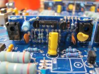
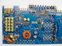
If you want to determine if the problem is before or after the driver board. Drive a strong signal into the amp and measure the AC voltage on the the resistors R85 and R63. The AC voltage should vary with the input volume from the signal source. If they are not the same (or one has essentially no AC voltage), the problem is before the driver board. To test the driver board and components beyond, you can use a small wire to connect between R63 and R85. Make the connections on the ends of the resistors closest to the yellow capacitors. If the two channels work well wired in that way, you can trace the path back to see where signal is being lost (after removing the jumper).
Before connecting the jumper, confirm that neither resistor has any significant DC voltage. Both should have essentially no DC voltage.
As it was mentioned, it's easy to damage the pads for these connections. When heating the solder, do not apply pressure to the pads with the tip of the iron. Allow the iron to melt into the solder but hold it so that it never touches the pads. The solder will conduct enough heat to allow all of the solder to be heated and removed. When applying new solder, you will have to touch the pads but you should apply as little pressure as possible.
You have to use a soldering iron to melt the solder. You could use a hot-air rework station but if not used correctly, it too can cause damage. A heat gun would probably damage a large area of the board before the solder got hot enough to be fully removed.
You don't have to let contact cleaner dry before testing. You need to work the switches back and forth 50-100 times while monitoring the output to see if the audio begins to play through. You can test again after the solvent has evaporated from the contact cleaner but most contact cleaners leave a lubricating/protective residue that remains wet for months (or more).
The smaller/lower profile switches will generally self-clean as you work them back and forth (especially with contact cleaner) but the larger 2-position switches often will not be cleaned by working them. The smaller switches use a sliding contact. The larger ones work more like a toggle switch so there is no wiping action between the contacts. They have to be replaced or cleaned by disassembling and manually cleaning them.
Most fluxes for electronics are not significantly corrosive and don't necessarily have to be cleaned but cleaning with acetone and cotton swabs makes the work look better and makes it easier to see problems like solder bridges and bad solder connections. Flux used for plumbing IS corrosive and should not be used on electronic components or circuit boards.
If you want to determine if the problem is before or after the driver board. Drive a strong signal into the amp and measure the AC voltage on the the resistors R85 and R63. The AC voltage should vary with the input volume from the signal source. If they are not the same (or one has essentially no AC voltage), the problem is before the driver board. To test the driver board and components beyond, you can use a small wire to connect between R63 and R85. Make the connections on the ends of the resistors closest to the yellow capacitors. If the two channels work well wired in that way, you can trace the path back to see where signal is being lost (after removing the jumper).
Before connecting the jumper, confirm that neither resistor has any significant DC voltage. Both should have essentially no DC voltage.
1moreamp is absolutely correct about the feb boards needing the solder work. I did it to a ss 405 that has two channels cutting on and off with bumps or taps on the chassis.
Do this then test it.
Do this then test it.
If you want to determine if the problem is before or after the driver board. Drive a strong signal into the amp and measure the AC voltage on the the resistors R85 and R63. The AC voltage should vary with the input volume from the signal source. If they are not the same (or one has essentially no AC voltage), the problem is before the driver board. To test the driver board and components beyond, you can use a small wire to connect between R63 and R85. Make the connections on the ends of the resistors closest to the yellow capacitors. If the two channels work well wired in that way, you can trace the path back to see where signal is being lost (after removing the jumper).
Before connecting the jumper, confirm that neither resistor has any significant DC voltage. Both should have essentially no DC voltage.
Now THIS is exactly what I was looking for. Maybe its the engineer in me, but I like to determine the exact issue before starting the repair. While I'm all for repairing soldered connections when they are bad, I don't want to just start reflowing connections if I don't know for sure if it even is the solder that is the problem. Diagnostics like that is the direction I was wanting to go, to actually pinpoint where the problem lies. Are there any typical steps in determining a faulty switch?
I tapped with a screwdriver handle and wiggled the FEB boards while on the test bench and nothing happened with the sound output. I even shook the entire assembly hoping to get the sound to come back in like before when I tilted the amp, but nothing. If it were the soldered joints in the FEB board, I would have expected it to cut back in when I was wiggling and tapping the FEB board. I personally am leaning towards a faulty switch or a faulty solder at a switch.
I will do exactly as you describe as soon as I get a chance again, and report back. In the meantime, if there are any tips on actually checking voltage for switches (continuity/voltage) that would be cool too.
New development over lunch. On the test bench I was poking and prodding the FEBs again hoping yesterday was a fluke. I then pressed on the mainboard next to the FEB and voila! Sound cut in as long as I hold the mainboard down. This has in fact, in my opinion, solidified the cause as being weak joints on the FEB-to-mainboard. Now to get a solder sucker and begin the resolder 🙂 Thanks everyone for the help!
1moreamp told me about those reflowing solder joints,i didn't believe him at first because they all looked okay/good. But i went ahead and redid all the feb boards and viola .... No more cutting on and off on any of the channels. This is something I'll remember from now on for when i do run onto another soundstream amp.
- Status
- Not open for further replies.
- Home
- General Interest
- Car Audio
- Soundstream Reference 644s - Channel 2 not working