This amp came back after I rebuilt it and the sub channel failed.
Prior to the return, I rebuilt 3 of the 5 channels. Checked driver cards, rebuilt the sub driver card. Replaced all TIP102, TIP107, MPSA14, and 0.27ohm emitter resistors. Replaced ALL switches. Cleaned all controls. Redid heat compound and everything else. The amp passed all tests and I sent it off to a customer.
About two weeks go by and customer says amp is blowing fuses.
Returned to me, and I found the entire 5th channel blown. All TIP102/107 replaced again. Also put in a brand NEW FED1 driver card this time, and two new Rectifiers for the 5th channel. Amp is working again and I've tested it down to 1.5ohm in high power mode.
The customer was running it at 1.5 ohms under High Power mode, with two JL13tw3-3 subwoofers in a sealed box. Asking a lot from this amp with those dubs IMO; those subs are looking for about 1000w whereas this amp can only give about ~300w. Who knows what input level was used.
The sub channel to my surprise is running +-49vDC rail. Thats just shy of the 50v rail caps, and the TIP102/107 are only rated for 100v. Come to think of it, 49vDC is the highest rail voltage I've ever seen in a soundstream reference amp.
If I increase R102 or R104 in the PS circuit a few K ohms will that reduce rail a bit? SOA seems kind of tight with TIP102 at 49vDC otherwise. I had done something similar in a test amp prior - playing with rail voltage as an experiment. Not sure if this is the right thing to do. It would be nice to lower rail voltage to about 45vDC in high power mode.
What about using slightly higher rated, say 0.68ohm emitter resistors? Would that increase stability at all? I know the Class A amps run 1.0ohm + bypass diodes.
Thanks
The 405 schematic does not show sub rail voltage... but the 705S shows +-38 and +-28 depending on the current switch setting.
Does the rail voltage drop if you drive the amp to low power into a load?
The 405 has a higher transformer ratio for the sub channel so the rail voltage will be higher.
What was the 12v supply voltage when you read 49v?
Do you see excessive spikes/ringing on the primary windings of the transformer?
The 405 has a higher transformer ratio for the sub channel so the rail voltage will be higher.
What was the 12v supply voltage when you read 49v?
Do you see excessive spikes/ringing on the primary windings of the transformer?
Un-regulated supply. 97.5vDC rail on the sub channel at 14.5vDC supply. When I drop to 12.5v supply rail goes to ~80vDC.
Heres what the primary looks like at 5v/Div & 1uS. I positioned the trace to the bottom so more detail can be seen.
Heres what the primary looks like at 5v/Div & 1uS. I positioned the trace to the bottom so more detail can be seen.
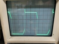
Are you sure that's at 1us? That would be a very high frequency.
You can try varying the value of R103 but if you do and increase the deadtime, there will be more stress on the primary rail caps.
You can try varying the value of R103 but if you do and increase the deadtime, there will be more stress on the primary rail caps.
Yes that is at 1us. Is something wrong there you think?
R103 13k. With an 11k the sub rail voltage dropped to about 95.5v. The other rails in the amp only dropped by about 1.25v.
Everything looks the same otherwise.
Ill probably just leave things there and send it.
thanks
R103 13k. With an 11k the sub rail voltage dropped to about 95.5v. The other rails in the amp only dropped by about 1.25v.
Everything looks the same otherwise.
Ill probably just leave things there and send it.
thanks
According to the components used for timing, I calculated a 30k oscillation frequency at the output of the IC. Measure it with a multimeter. Compare to other SS amps if you have any others on hand.
- Home
- General Interest
- Car Audio
- Soundstream Reference 405