Hi everyone,
I have a SOUNDSTREAM LW4.500 amplifier that powers on, is not in protection mode, and all voltages are present as they should be.
However, it doesn’t produce any sound output, and without a schematic, I can’t figure out the path the input signal takes.
Can anyone help me?
Thanks!
Giovanni
I have a SOUNDSTREAM LW4.500 amplifier that powers on, is not in protection mode, and all voltages are present as they should be.
However, it doesn’t produce any sound output, and without a schematic, I can’t figure out the path the input signal takes.
Can anyone help me?
Thanks!
Giovanni
Attachments
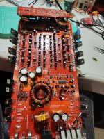
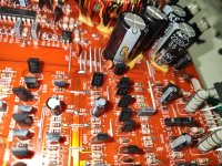
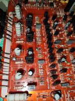
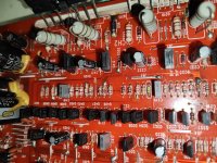
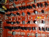
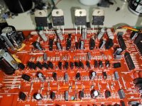
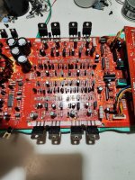
Can you post a high resolution image of the audio section showing all of the driver transistors?
If this is like some of the other amplifiers that look like this, this could be very time consuming to repair if you want good reliability.
If this is like some of the other amplifiers that look like this, this could be very time consuming to repair if you want good reliability.
Hi Perry,
Glad to hear from you! Here are some photos of the amp section; I hope the resolution is high enough.
Here’s something strange: since all the channels are "muted," I was hoping it might be a simple muting transistor fault, but it seems the problem might be more complicated.
Using the oscilloscope, I traced the audio signal from the input up to Q402 (for channel 4 – Q302 for the opposite channel). It seems the preamp sections, filters, and audio switches are working fine. I couldn’t do much more than that because I’m getting confused while tracing the signal. It’s challenging to follow on the red board without schematics 🙂
Thanks
Giovanni
Attachments
-
 IMG_20241227_055939.jpg662.6 KB · Views: 25
 -
 IMG_20241227_055655.jpg602.4 KB · Views: 21
 -
 IMG_20241227_055640.jpg620.1 KB · Views: 20
 -
 IMG_20241227_055633.jpg625.7 KB · Views: 20
 -
 IMG_20241227_055617.jpg670.6 KB · Views: 19
 -
 IMG_20241227_055608.jpg698.4 KB · Views: 22
 -
 IMG_20241227_055534.jpg761.2 KB · Views: 22
Do ahy of the low-designation (Q00 or Qx01...) have their emitter connected to the secondary ground?
The bad news on this amp is that if all solder connections that are soldered on both sides of the board on a single terminal are not repaired (properly, not just resoldered), the amp absolutely will not be reliable. That can be addressed later if we find the muting problem.
The bad news on this amp is that if all solder connections that are soldered on both sides of the board on a single terminal are not repaired (properly, not just resoldered), the amp absolutely will not be reliable. That can be addressed later if we find the muting problem.
Hi Perry,
now I understand your concern about this repair. At the moment, I haven’t verified "one pin connections side to side," as I’m focusing only on the muting problem.
Alright, I’ll get back to you after checking all the "low-designation" transistors.
For now, thank you for sharing your experience; it’s greatly appreciated !!!
Giovanni