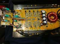
Have a Soundstream DTR4.500 amplifier that has uneven levels of output on all four channels. Unsure where in the preamp section things are going wrong. I can see even levels of AC input from the RCA terminals to the preamp end of the board, and I can see unequal levels of output coming from the preamp section towards the output stage.
I cleaned all switches and potentiometers with no results. I don't see any obviously burnt/damaged components. The only thing I can think of is 074C ICs but without a schematic I would likely do more damage than is necessary. Can anyone guide me where to check this issue?
I cleaned all switches and potentiometers with no results. I don't see any obviously burnt/damaged components. The only thing I can think of is 074C ICs but without a schematic I would likely do more damage than is necessary. Can anyone guide me where to check this issue?
Attachments

You need to document the precise AC voltage levels on each channel at several points (RCA to main board, into and out of preamp board).
Set all gains at max and all crossovers to flat.
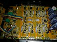
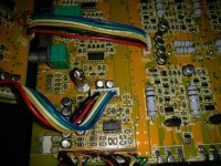
All of that fixative needs to be removed. It appears to be corrosive and is likely borderline conductive.
Set all gains at max and all crossovers to flat.
All of that fixative needs to be removed. It appears to be corrosive and is likely borderline conductive.
Inputting a 100hz test tone playing from a Pioneer CD player at volume 55 so that the AC voltage reading at the preamp section input plug coming from the RCAs is as close to 1v as possible. Using the same single RCA, one RCA input plug at a time. I was unsure how to list the voltages of each channel as they pass through the amplifier so each channel is :
R Front / L Front / R Rear / L Rear
preamp connector plug from RCA inputs:
0.99 / 0.97 / 0.99 / 1.0
R Front / L Front / R Rear / L Rear (RESISTORS AFTER CAPACITORS BETWEEN PREAMP PLUG AND U701)
R721 0.96 / R731 0.91 / R756 0.75 / R757 1.0
R Front / L Front / R Rear / L Rear
U701 (074C) (IC CLOSEST TO THE PREAMP SECTION INPUT PLUG)
Pin3 Pin2 Pin1 / Pin5 Pin6 Pin7 / Pin10 Pin9 Pin8 / Pin12 Pin13 Pin14
0.01 0.01 0.61(OUT) / 0.49 0.49 0.92(OUT)/ 0.01 0.01 1.04(OUT) / 0.45 0.45 0.79(OUT)
R Front / L Front / R Rear / L Rear (CAPACITORS BETWEEN PRE AND AMP SECTIONS)
C754 / C764 / C770 / C771
7.78-2.77 / 8.85-6.76 / 8.6- 4.48 / 8.04-3.08
R Front / L Front / R Rear / L Rear (GATE LEGS OF OUTPUTS)
Q311-312 / Q411-412 / Q111-112 / Q211-212
22.47 / 25.90 / 8.85 / 23.51
R Front / L Front / R Rear / L Rear
preamp connector plug from RCA inputs:
0.99 / 0.97 / 0.99 / 1.0
R Front / L Front / R Rear / L Rear (RESISTORS AFTER CAPACITORS BETWEEN PREAMP PLUG AND U701)
R721 0.96 / R731 0.91 / R756 0.75 / R757 1.0
R Front / L Front / R Rear / L Rear
U701 (074C) (IC CLOSEST TO THE PREAMP SECTION INPUT PLUG)
Pin3 Pin2 Pin1 / Pin5 Pin6 Pin7 / Pin10 Pin9 Pin8 / Pin12 Pin13 Pin14
0.01 0.01 0.61(OUT) / 0.49 0.49 0.92(OUT)/ 0.01 0.01 1.04(OUT) / 0.45 0.45 0.79(OUT)
R Front / L Front / R Rear / L Rear (CAPACITORS BETWEEN PRE AND AMP SECTIONS)
C754 / C764 / C770 / C771
7.78-2.77 / 8.85-6.76 / 8.6- 4.48 / 8.04-3.08
R Front / L Front / R Rear / L Rear (GATE LEGS OF OUTPUTS)
Q311-312 / Q411-412 / Q111-112 / Q211-212
22.47 / 25.90 / 8.85 / 23.51
Last edited:
Will do that in the morning. Might explain why there is very low gate drive on that channel.
Any ideas about the uneven levels of the other channels? Maybe something else I can check once I get back to the amp?
Any ideas about the uneven levels of the other channels? Maybe something else I can check once I get back to the amp?
But the audible output of the individual channels is noticably different. Left Front is clearly the loudest, Right Front and Left Rear were both less loud but there was even an audible difference between those two. Right Rear was barely audible but the corroded via/low gate drive should explain that.
Are you saying that the other three channels should sound virtually the same despite the slightly different AC voltage readings?
Other than the low gate drive on the Right Rear channel, are these readings about what you would expect?
Are you saying that the other three channels should sound virtually the same despite the slightly different AC voltage readings?
Other than the low gate drive on the Right Rear channel, are these readings about what you would expect?
You have one low channel. The numbers you posted don't show anything that would be audibly different for 3 channels.
The gate drive on a linear amp will change with the load. It's not like a switching power supply or class D amp where the amplitude of the drive is constant.
The gate drive on a linear amp will change with the load. It's not like a switching power supply or class D amp where the amplitude of the drive is constant.
I repaired the corroded via on the channel with low AC voltage on the output gates but that one channel still remains weaker than the other three. I don know how to go about getting that channel's AC voltage up to the level of the other three.
I checked the DC voltage on all the resistors, transistors and capacitors within the individual channels, but they seem very similar and I can't figure out the AC voltage issue.
How do I go about figuring this out?
I checked the DC voltage on all the resistors, transistors and capacitors within the individual channels, but they seem very similar and I can't figure out the AC voltage issue.
How do I go about figuring this out?
The difference in AC voltage vis similar to post#3. The normal channels have 20-25v AC while the weak channel would have 6-8v AC when driven with the same signal.
I can't figure out where the loss is occurring. The AC voltage vis low all over the channel. I tried swapping the diodes D102 and D302 but it made no difference.
I am not sure where the low signal of 2.77VAC that comes from the caps like C754 turns into 22.47VAC.
I can't figure out where the loss is occurring. The AC voltage vis low all over the channel. I tried swapping the diodes D102 and D302 but it made no difference.
I am not sure where the low signal of 2.77VAC that comes from the caps like C754 turns into 22.47VAC.
You're showing the voltage on the gate legs of the outputs. That's not a good reference. You need to measure the output at the speaker terminals.
The voltages seem inconsistent throughout. That's fairly normal where there are potentiometers in the circuit.
The numbers feeding the lowest channel (last set of numbers) has the highest input (previous numbers) of all of the channels.
The voltages seem inconsistent throughout. That's fairly normal where there are potentiometers in the circuit.
The numbers feeding the lowest channel (last set of numbers) has the highest input (previous numbers) of all of the channels.
When I am checking for the AC voltage it is the same at all the points in the channel where it is present. The voltage is the same on leg1 and leg3 of the output transistors as well as the bias transistors and on many resistors, capacitors and transistors within the channel. I am using the ground terminal for probe ground.
I was trying to find on one of the good channels, where the low voltage stopped and the high voltage started but I couldn't find any one particular component that had low volts on one side and high volts on the other side except the diode at D102 and D302. I swapped them but with no change in the problem.
I was trying to find on one of the good channels, where the low voltage stopped and the high voltage started but I couldn't find any one particular component that had low volts on one side and high volts on the other side except the diode at D102 and D302. I swapped them but with no change in the problem.
1 and 3 MAY have the same voltage but the gate/base drive isn't always going to follow the emitter.
How do I go about fixing this problem?
I don't understand why the AC voltage in the output channel is different? I swapped outputs and gate drive transistors with a strong AC voltage channel and the problem is unchanged. I don't understand where that increase in voltage occurs so I cannot diagnose the faulty component/issue. Help please?
I don't understand why the AC voltage in the output channel is different? I swapped outputs and gate drive transistors with a strong AC voltage channel and the problem is unchanged. I don't understand where that increase in voltage occurs so I cannot diagnose the faulty component/issue. Help please?
An un-even output signal level, if the low channel is clean, undistorted is RARELY going to be an issue in the amplifiers section. It could be at the input to the amplifier circuit, maybe the muting transistor if it has one. The problem is likely in the circuit before the amplifier stage.
You're going to have to do the heavy lifting here. You will need to look at every stage at the input and output. Set the controls however they need to be set (even if not the same) to get the input of each level of each stage as close to identical as possible then look at the output stage of every channel. Where is the biggest loss. Start there.
You're going to have to do the heavy lifting here. You will need to look at every stage at the input and output. Set the controls however they need to be set (even if not the same) to get the input of each level of each stage as close to identical as possible then look at the output stage of every channel. Where is the biggest loss. Start there.
- Home
- General Interest
- Car Audio
- Soundstream DTR4.500 with uneven output