Hi guys
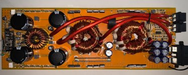
I'm working on this soundmagus PK1500.1, which came to my workbench with the output mosfets shorted, the 10uf 100v non-polar electrolytic capacitors blown, in addition to the 2200uf 100v blown, the 1uf 100v polyester capacitors blown coil output shorted and resistor R294 open.
Once the board has been cleaned and all the new components have been installed, in addition other soundmagus vs1500 output coil, the amplifier has a standby consumption of more than 20 amps, even short-circuiting ALL 640n of output in less than 2 seconds. In addition to high frequency noise in the output coil. Something very strange.
But by removing the 50ohm R294 resistor, the draw drops to 1.4 amps, which is normal for this amp. The output pulses appear very clean and stable at 122khz, but when I connect a speaker to it, it has very unpleasant noise and DC voltage spikes.
I have reviewed solderings, reviewed all the existing diodes and transistors on the board, resistors and some ceramic capacitors.
It's a very strange problem that I never get to my table on any other amp.
Does anyone have any idea what may be happening? I've been working on it almost daily for more than 2 weeks and I can't find the problem.
Thanks
Attachments
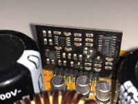
Post a good quality, high resolution photo of the driver board.
Is the audio clean going into the driver board?
Is the audio clean going into the driver board?
not necessary, removing R294 everything is normal, the output pulses are correct and clean, you just have that strange noise from the speakers.
I don't know what R294 is on this amp. Is it exactly the same as the SLA1500?
Does heating/cooling of anything on the board make a difference?
Does heating/cooling of anything on the board make a difference?
the SLA1500 is somewhat different from the PK1500. The only thing that I have noticed that heats up are the 640n output transistors, one side more than the other .. but the pulses are correct without r294.
If you leave me an email, I can send you the schematic of this amplifier.
thanks
If you leave me an email, I can send you the schematic of this amplifier.
thanks
babin_perry@yahoo.com
I was asking that if YOU heated/cooled various components, did that make the amp behave any differently?
I was asking that if YOU heated/cooled various components, did that make the amp behave any differently?
Yes, I heated the whole board, especially in ICs, semiconductors and smd capacitors and I didn't get any variation in the current behavior of the amplifier.
you already have the schematic in your email.
Thank you.
you already have the schematic in your email.
Thank you.
Got it.
Without that resistor, the feedback is lost and you could expect the amp to do strange things.
Is it possible that the inductor is shorted?
Are any of the new capacitors heating up?
Is the output at the speaker terminals clean and essentially free of high frequency noise?
Have you tried replacing U3 or C151?
I have changed U3 and c151 for new components.
new capacitors do not heat any.
the noise at the output is like knocking, I do not appreciate high frequency noise.
new capacitors do not heat any.
the noise at the output is like knocking, I do not appreciate high frequency noise.
Are all of the rest of the capacitors in the feedback filter within tolerance?
Will the outputs survive if you clamp them to the heatsink?
What about adding a limiter? If a resistor in the B+ line doesn't work, maybe you can insert one in series with the rectifier output.
If you do that, you may need to defeat the delay/mute so the rail caps aren't able to charge before the output driver starts.
hii
All capacitors are brand new ....
It does not matter which one is on the heatsink, short-circuit the 640n if the amplifier does not turn off in less than 2-3 seconds .....
I don't know if it would be a good option to install that resistance in the B + circuit .........
This amp has me totally baffled .........
- Home
- General Interest
- Car Audio
- Soundmagus PK1500.1 output section problem