Hi
Unfortunately, one of by beloved speaker is not working.
I found only 37V DC on the membrane polarization plug instead of 310V.
I guess it's one dead diode or many.
The problem is that I can't identify this diode : it is only marked 68.
It's an uncommon kind : several stacked circumflex accents instead of one ring.
I mailed to the company and yet I got no answer.
So, can you tell me what kind of diode may I use in replacement and possibly its specifications ?
Besides, I did not measure the same DC voltages as on the PCB.
Regards.
Attachments
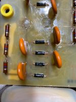
The diodes here are being used in a capacitor-diode voltage multiplier. Any silicon diode of sufficiently high voltage rating will do.
Actualy, egellings, the resistors are 120Meg : brown-red-violet.
I had to connect them in parallel to be able to measure (Fluke 15B).
Are you sure, HumbleDeer, about the diodes : I don't want to destroy these tremendous speakers.
Thank you two for your support.
I had to connect them in parallel to be able to measure (Fluke 15B).
Are you sure, HumbleDeer, about the diodes : I don't want to destroy these tremendous speakers.
Thank you two for your support.
Are you talking about V2 or at one of the outputs?37V DC on the membrane polarization plug instead of 310V.
Bias output is more typically in the thousands of volts, and can't be measured with a standard voltmeter.
Your description isn't clear enough to give good advice. We need to know exactly what you measured at what points and how. There are AC and DC points in a voltage multiplier.
Knowing what the AC source feeding the multiplier is would also be helpful.
In voltage multipliers, the voltage requirements for the diodes and capacitors are the same: 2x the peak input voltage. (see attached app note)
Can you see the voltage ratings of the caps? I have a pic for a similar looking bias supply from a model A2x and it shows 3kV.

If the capacitor voltage ratings are < 4kV, I would recommend the Vishay GP02-40 4kV diodes.
https://www.mouser.fr/c/?q=GP02-40
Can you see the voltage ratings of the caps? I have a pic for a similar looking bias supply from a model A2x and it shows 3kV.
If the capacitor voltage ratings are < 4kV, I would recommend the Vishay GP02-40 4kV diodes.
https://www.mouser.fr/c/?q=GP02-40
Attachments
If the color is violet, you are correct. That color band seemed blue to me on my screen. How can they cram so many ohms into such a tiny package, hey?Actualy, egellings, the resistors are 120Meg : brown-red-violet.
I had to connect them in parallel to be able to measure (Fluke 15B).
Are you sure, HumbleDeer, about the diodes : I don't want to destroy these tremendous speakers.
Thank you two for your support.

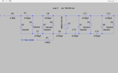
here is the complete circuit but I don't understand the voltages calculated by Ltspice.
On the bench, with 40V AC through a variac :
PCB not connected :
5.8V AC at the primary, 207V AC at the secondary
PCB connected :
3.2V AC at the primary, 124V AC at the secondary, 10V DC at output R1,
18V DC at output R3.
On the bench, with 40V AC through a variac :
PCB not connected :
5.8V AC at the primary, 207V AC at the secondary
PCB connected :
3.2V AC at the primary, 124V AC at the secondary, 10V DC at output R1,
18V DC at output R3.
Attachments
Can you clarify what and how you were measuring?Unfortunately, one of by beloved speaker is not working.
I found only 37V DC on the membrane polarization plug instead of 310V.
1) Was the 310V measured on the working speaker and the 37VDC measured on the speaker that is not working?
2) Did you have both the of the polarization plugs disconnected? both bass and treble plugs. (This is important to make sure any leakage in the wiring or either panel isn't loading down the multiplier)
3) When measuring the voltage, were you connecting your FLUKE 15B directly to the polarizing plug and ground as shown below?

If the answer to question 3) is "Yes", the 10Meg input impedance of the 15B formed a voltage divider with the 360Meg bias resistors.
The bass bias voltage would then be 310VDC * (370/10) = 11.5kVDC, meaning each of the Capacitors had about 2.9kV across them...just under their 3kV rating.
To make more accurate measurements of the HV bias supply you will need to use a HV probe that can handle the high voltages and has a high input impedance (1000Meg) so it won't load down the HV multiplier which has an inherent weak current capability. You can often find them used on ebay for < $100
https://www.fluke.com/en-us/product/accessories/probes/fluke-80k-40
https://www.ebay.com/itm/176767671886
Last edited:
Thank you for your concern.
First thing first : 37V was measured on the incompletely wired supply.
1) 65 V DC, this time, was measured on the faulty and discharged power supply
(without a speaker connected).
300 V DC on the good power supply (also discharged).
Besides, both speakers work perfectly.
2) Both plugs are disconnected.
3) Yes, as shown in the photo.
Sorry, I don’t understand the formula 310VDC * (370/10) = 11.5kVDC, can you explain it to me ?
Were does come from the 310 & 370/10 values ?
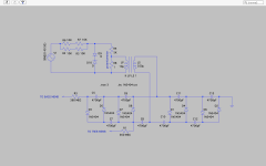
As you noticed, actually the schematic is incomplete: ground is also connected to the secondary ’s
center tap of the output transformers (which go to the treble & bass stators).
The primary, of course, is connected to the amplifier output.
I'm a little hesitant about the HV probe: its cost is significant for a very occasional use.
First thing first : 37V was measured on the incompletely wired supply.
1) 65 V DC, this time, was measured on the faulty and discharged power supply
(without a speaker connected).
300 V DC on the good power supply (also discharged).
Besides, both speakers work perfectly.
2) Both plugs are disconnected.
3) Yes, as shown in the photo.
Sorry, I don’t understand the formula 310VDC * (370/10) = 11.5kVDC, can you explain it to me ?
Were does come from the 310 & 370/10 values ?
As you noticed, actually the schematic is incomplete: ground is also connected to the secondary ’s
center tap of the output transformers (which go to the treble & bass stators).
The primary, of course, is connected to the amplifier output.
I'm a little hesitant about the HV probe: its cost is significant for a very occasional use.
I use this: https://www.aliexpress.com/item/100....order_list.order_list_main.10.5aa75e5bbVPswx
A HV 10G resistor in series with a standard DMM (10M) makes a nice 1000:1 divider, 1V = 1000V
The syringe I stole from a junky, it's just for show.


A HV 10G resistor in series with a standard DMM (10M) makes a nice 1000:1 divider, 1V = 1000V
The syringe I stole from a junky, it's just for show.
The syringe idea is one of the coolest things that I have seen in some time... unless the resistor gets really hot. But it gives a temporary way to safely do this.
Unlikely: 223KV are needed to reach the nominal dissipation of 5W 🙂... unless the resistor gets really hot...
What are you discharging? The panels? or the power supply.Thank you for your concern.
First thing first : 37V was measured on the incompletely wired supply.
1) 65 V DC, this time, was measured on the faulty and discharged power supply
(without a speaker connected).
300 V DC on the good power supply (also discharged).
2) Both plugs are disconnected.
3) Yes, as shown in the photo.
Is the power supply plugged in when you measure the 300VDC?
So, you can hook the good power supply up to either speaker and they both work?Besides, both speakers work perfectly.
If so, this would confirm that the problem is not the panels but with the HV supply.
310VDC is the value from Post#1 that you measured on your Fluke 15B meter.Sorry, I don’t understand the formula 310VDC * (370/10) = 11.5kVDC, can you explain it to me ?
Were does come from the 310 & 370/10 values ?
The formula is the inverse of a resistive voltage divider, since we know the output voltage and we want to calculate the input voltage.
https://www.digikey.com/en/resources/conversion-calculators/conversion-calculator-voltage-divider

Vin = Vout * (R1 + R2) / (R2)
R1 = 360 Meg
R2 = 10 Meg
10 = R2, the input impedance of the 15B in Megs
370 = (R1 + R2) in Megs
LTSpice results show the same thing if a 10Meg resistor is included to model the input impedance of the Fluke 15B.
From the plot, you can see that each capacitor has almost 3kV across it.

faulty and discharged power supply
RESP : it means PS not loaded by one speaker, all measurements made when there is no speaker plugged in
Is the power supply plugged in when you measure the 300VDC ?
RESP : PS plugged in 40VAC
If so, this would confirm that the problem is not the panels but with the HV supply.
RESP : YES
RESP : it means PS not loaded by one speaker, all measurements made when there is no speaker plugged in
Is the power supply plugged in when you measure the 300VDC ?
RESP : PS plugged in 40VAC
If so, this would confirm that the problem is not the panels but with the HV supply.
RESP : YES
- Home
- Loudspeakers
- Planars & Exotics
- SOUNDLAB A6