It looks like the output filter isn't doing its job.
Is this equal in amplitude to the rail-rail oscillation on the output transistors?
Where is the scope grounded?
Is this equal in amplitude to the rail-rail oscillation on the output transistors?
Where is the scope grounded?
Yes I am getting same amplitude and frequency on the inductor, from the side connected to outputs.
I am connecting scope ground to primary ground.
I am connecting scope ground to primary ground.
Are you using a resistor load? If not, the inductors won't filter as they should.
Does the amp have a bridged output? If so, you can't properly measure it without a differential probe.
Does the amp have a bridged output? If so, you can't properly measure it without a differential probe.
Yes it has clean DC. Picture attached. Black probe on primary ground and probed on capacitor positive terminal.Do you have clean DC on the rail caps?
Attachments
Did you try (carefully) to connect a load across the speaker terminals?
If so, did the signal you're seeing change?
With all of what I see, I'd expect the output filter caps to be burning. Are they heating up?
If so, did the signal you're seeing change?
With all of what I see, I'd expect the output filter caps to be burning. Are they heating up?
Yes connected 4ohms resistor and the signal is same. Capacitors remaining cool.
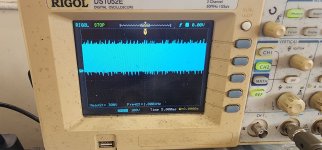
Also tried with math function in Oscilloscope and probed across speaker terminals that thick wave line shows same way.
Also tried with math function in Oscilloscope and probed across speaker terminals that thick wave line shows same way.
This is not unusual. The signal should be measured between the two speaker output, as noted. Difficult to do without a differential probe.
What you could try is measure with two probes on either speaker connection, and set the scope to 'subtract', that will give you the true output voltage.
Be sure the probes are properly adjusted and both channels set to same voltage setting.
Jan
What you could try is measure with two probes on either speaker connection, and set the scope to 'subtract', that will give you the true output voltage.
Be sure the probes are properly adjusted and both channels set to same voltage setting.
Jan
What happens if you desolder those jumpers?
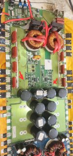
What audio driver ICs are they using in this amp?
Closeup photo of audio drive components?
What audio driver ICs are they using in this amp?
Closeup photo of audio drive components?
I can confirm that the jumpers should stay.No I am not using resistor nor is connected to any speaker. In the picture I saw company cut the board but then somebody made a solder jumper. Is the jumper correct?
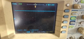
Have you ever seen this sort of output? It appears that the inductors are shorted and the output caps open (or their circuit on the board open).
I'm not arguing about the jumpers but why would they go through the effort to cut all of that copper, then add the jumpers? Was this done on other amps of this model?
I'm not arguing about the jumpers but why would they go through the effort to cut all of that copper, then add the jumpers? Was this done on other amps of this model?
I really dont know why they cut the traces. A long time ago they sent me an identical amp with the same traces cut. As far as i know it still works after 4-5 years. These early SD designs were a bit weird and unstable. Unfortunately, among other things, all my notes were stolen and i nave nothing on this amp


- Home
- General Interest
- Car Audio
- Soundigital amp output wave